System and method for performing adaptive modification of rapid prototyping build files

a technology of rapid prototyping and build files, applied in the direction of computer control, program control, instruments, etc., can solve the problems of stl file being considered faulty, virtual model generated by stl file may not be physically valid, and part may break under minor stresses

Active Publication Date: 2005-05-24
HEWLETT PACKARD DEV CO LP
View PDF3 Cites 56 Cited by
  • Summary
  • Abstract
  • Description
  • Claims
  • Application Information

AI Technical Summary

Problems solved by technology

When these conditions are not satisfied, the STL file may be considered faulty and the virtual model generated by the STL file may not be physically valid.
There are other issues which relate directly to manufacturability.
Even if a file is mathematically ‘valid’, if the part walls are too thin, the part will break under minor stresses.
Faulty STL files can be the result of problems in the original CAD file or imperfections in the algorithm used to tessellate the CAD model into an STL file.
For example, a poor tessellation algorithm often results in disoriented facets that can lead to physical irregularities in the manufactured object.
Other problems occur because of mathematical rounding errors during the tessellation process.
If the rounding errors result in triangles that are too small, then gaps or holes may be formed in the model.
If the rounding errors result in triangles that are too large, then excess material may be deposited and the surface will be irregular.
Errors can also result from the CAD user's ignorance of STL file requirements regarding internal walls or the errors may be an artifact of the CAD design tool.
An internal wall problem does not hinder the building of the object but it may cause problems in the finished prototype.
The laser beam may polymerize the areas having internal walls twice, resulting in over-cure and possible warping of internal wall surfaces.
These and many other errors can result in reduced utility or even useless objects formed in freeform fabrication.
Finally, errors can be created in the process of generating rapid prototyping files from non-CAD processes.
However, because the original destination of the part was the screen, the original design is likely to contain errors that are invisible when displayed on screen, which prevent the part from being manufactured.
Zero-width walls are one such problem, and holes or inverted polygons (i.e., bad normals) are another problem.
The conversion process may introduce more problems, especially if the conversion can only handle a subset of the original file format.
VRML includes complex objects such as curves and two-dimensional ‘billboards’ with animated content, so converting these to a rapid prototyping format can range from hard to impossible.
One common approach is to have a rapid prototyping machine operator fix the errors by directly editing the STL file with an STL File editor tool, but there are several disadvantages to taking this approach.
Manually correcting STL files is time consuming, which adds to the cost of the finished prototype.
Also, operators occasionally create additional errors while fixing previous errors.
Therefore, most rapid prototyping machine operators are skilled at editing STL files intended for mechanical use, but these operators may not have experience in fixing STL files intended for other uses.
The problems associated with using these software programs are similar to the problems with using an operator.

Method used


Image

  • System and method for performing adaptive modification of rapid prototyping build files
  • System and method for performing adaptive modification of rapid prototyping build files
  • System and method for performing adaptive modification of rapid prototyping build files

Examples


Embodiment Construction

[0019]Reference will now be made to the exemplary embodiments illustrated in the drawings, and specific language will be used herein to describe the same. It will nevertheless be understood that no limitation of the scope of the invention is thereby intended. Alterations and further modifications of the inventive features illustrated herein, and additional applications of the concepts of the inventions as illustrated herein, which would occur to one skilled in the relevant art and having possession of this disclosure, are to be considered within the scope of the invention.

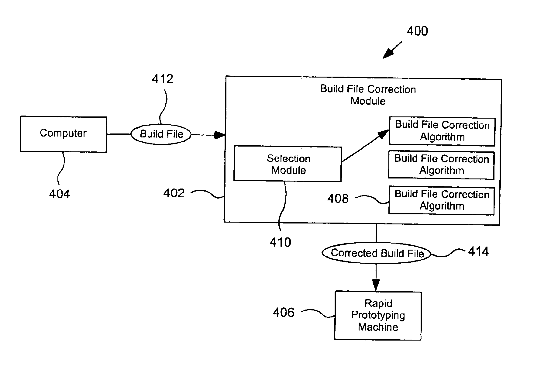
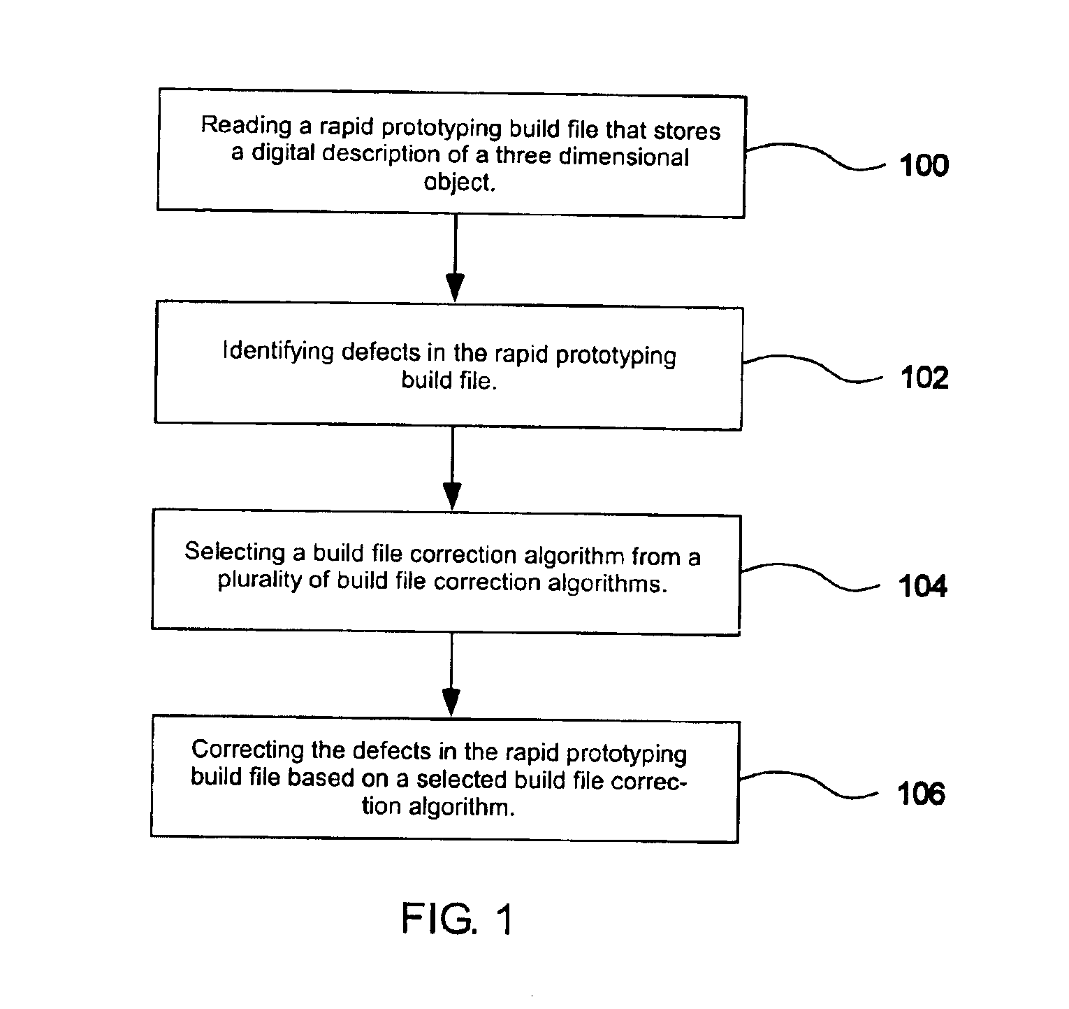
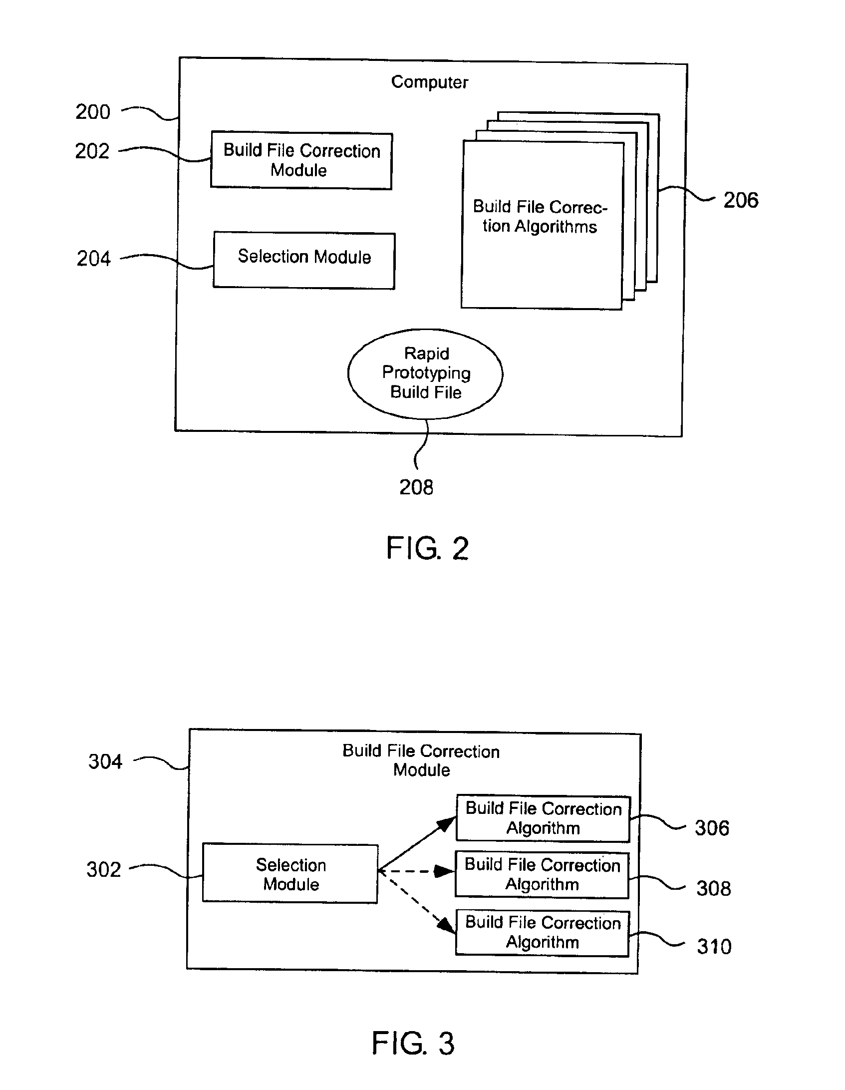
[0020]The present invention provides a system and method for performing adaptive modification of rapid prototyping build files. The invention allows a user or a computer to select a build file correction algorithm from a set of multiple correction algorithms, which provides greater flexibility to designers and engineers. This greater flexibility can help to better preserve the designer's intents and to build more a...


PUM

PropertyMeasurementUnit
defectsaaaaaaaaaa
mechanical precisionaaaaaaaaaa
durabilityaaaaaaaaaa

Abstract

A system and method is provided for performing adaptive modification of rapid prototyping build files. The method includes the step of reading a rapid prototyping build file that stores a digital description of a three dimensional object. The invention also includes the operation of selecting a build file correction algorithm from a plurality of build file correction algorithms. Defects in the rapid prototyping build file are identified and these defects are then corrected based on the selected build file correction algorithm.

Description

FIELD OF THE INVENTION[0001]The present invention relates generally to modifying rapid prototyping build files.BACKGROUND OF THE INVENTION[0002]Rapid prototyping is the name given to an assortment of related techniques used to fabricate physical objects from computer aided design (CAD) representations of the objects. Just as a printer can take a digital representation of an image and create a two dimensional hard copy, rapid prototyping machines can ‘print’, or add and bond materials in layers to form three dimensional hard objects. Other names for creating a three dimensional prototype in this manner include freeform fabrication, solid freeform fabrication, layered manufacturing, automated fabrication, solid imaging, and additive manufacturing.[0003]The techniques used in rapid prototyping offer numerous advantages over subtractive fabrication methods such as milling or turning. For example, an object with significant geometric complexity can be fabricated without the elaborate mac...

Claims


Application Information

Patent Timeline
Patent Type & Authority Patents(United States)
IPC IPC(8): G06F19/00G05B19/408
CPCB29C67/0088G05B19/4083G05B2219/49029G05B2219/35305G05B2219/35288B29C64/386B33Y50/00B33Y10/00
Inventor LOUGHRAN, STEPHEN A.
Owner HEWLETT PACKARD DEV CO LP
Why Eureka
Try Eureka