Auxiliary handle with a laser alignment device for drills

a technology of laser alignment and auxiliary handles, which is applied in the direction of portable drilling machines, instruments, manufacturing tools, etc., can solve the problems of difficulty in achieving accurate alignment, and achieve the effect of positioning the hole on the non-level surface more accurately

Inactive Publication Date: 2005-05-31
CHERVON INT TRADING
View PDF13 Cites 68 Cited by
  • Summary
  • Abstract
  • Description
  • Claims
  • Application Information

AI Technical Summary

Benefits of technology

[0009]One or more level bubbles can also be mounted on the sub-handle to indicate the relative position of the laser beam projected by the second laser generator as in horizontal, vertical or 45 degrees reference to horizontal plane. Thus, with the aid of the level bubbles of different position on the auxiliary handle and sub-handle, it is possible to position a hole on a non-level surface more accurately by horizontally, vertically or at 45 degrees referencing to a reference point.
[0010]An even further object of the present invention is to provide a sub-handle wherein the laser generator projects a laser beam backward to the drill. Thereby, the operator can take the target behind his or her back as basic reference during the work.

Problems solved by technology

Moreover, if the reference objects are far away, it is difficult to attain the alignment with precision.

Method used


Image

  • Auxiliary handle with a laser alignment device for drills
  • Auxiliary handle with a laser alignment device for drills
  • Auxiliary handle with a laser alignment device for drills

Examples


Embodiment Construction

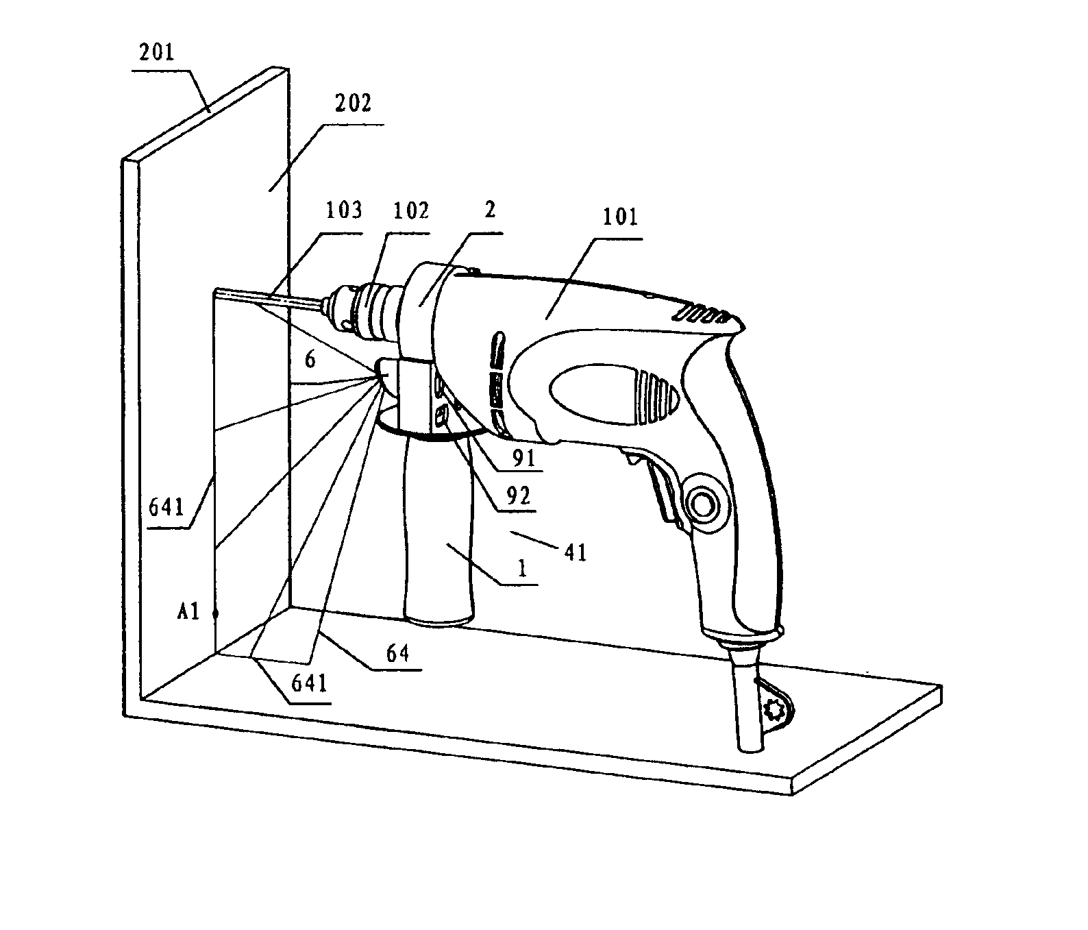
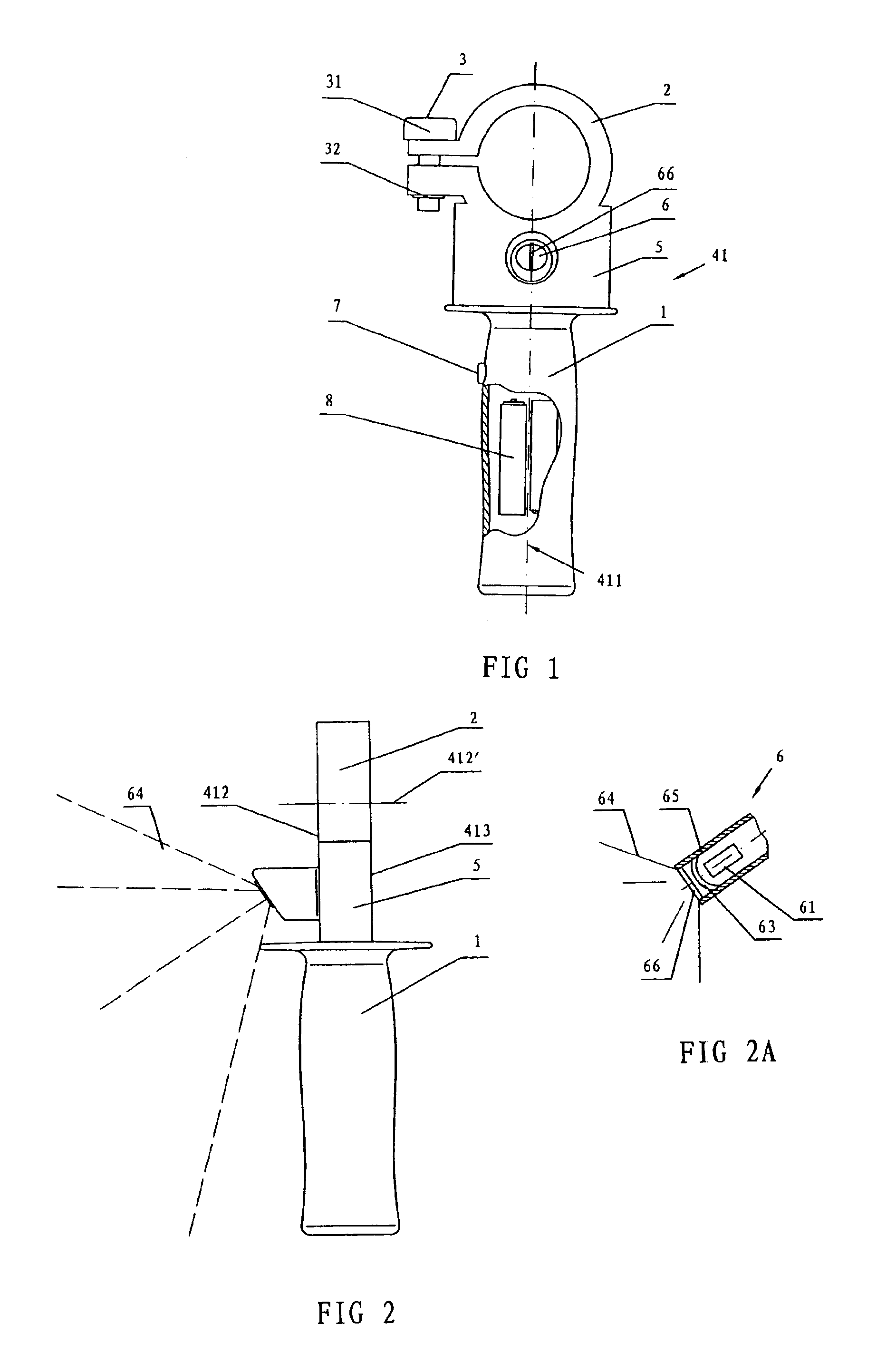
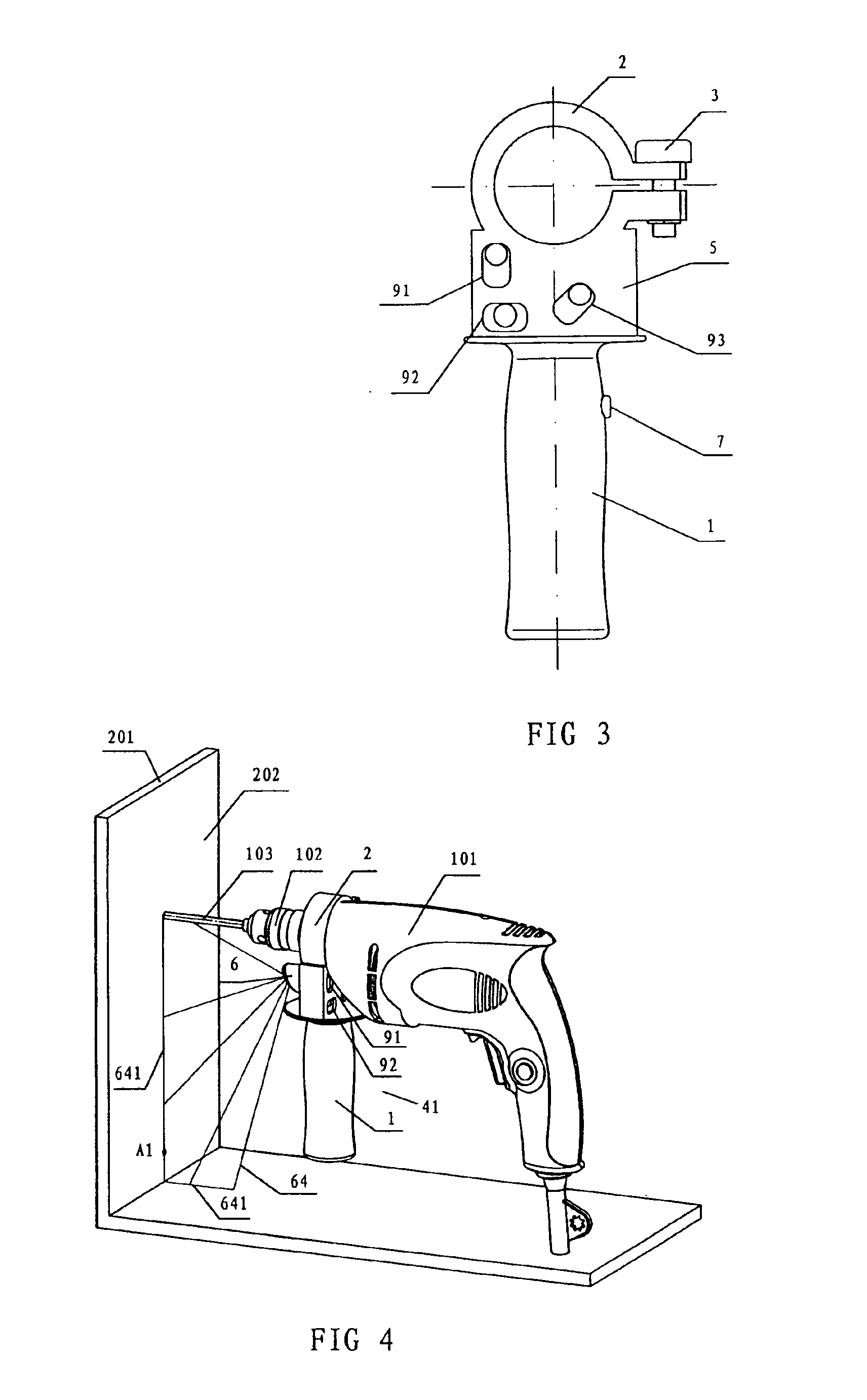
[0024]Referring to FIGS. 1-4, the auxiliary handle 41 of the present invention can be mounted on a drill 101 to position a reference point or a series of reference points on a work surface. The auxiliary handle 41 comprises a handle portion 1 for grasping, an opened collar 2 for mounting the handle 41 to a shoulder of the drill 101, and a clamp means 3 for locking or loosening the opened collar 2. The auxiliary handle 41 further comprises a first laser generator 6 positioned in the front face 412 of the auxiliary handle 41, a switch 7 used to turn on or turn off the first laser generator 6, a battery pack 8 to power the first laser generator 6, and clamp means 3 may comprise a bolt 31 and a nut 32. For the convenience of a left-handed person, it is preferable that the center axis 411 of the auxiliary handle 41 can be in a common plane with the drilling axis 412′ of the opened collar 2 when the opened collar 2 is secured to drill 101. In this manner, the center axis 411 is also in a ...


PUM

PropertyMeasurementUnit
angleaaaaaaaaaa
angleaaaaaaaaaa
elevation angleaaaaaaaaaa

Abstract

An auxiliary handle with a laser alignment device for drills comprises a grip portion for grasping, an opened collar which can be engaged with shoulder of the drill, and a clamp means for locking or loosing the opened collar. The auxiliary handle also comprises a first laser generator which can project a fanned planar laser beam, a battery pack which can be used to power the first laser generator, and a switch for turning on or turning off the first laser generator, the fanned laser beam which is projected by the first laser generator is in alignment with the central axis of the opened collar. Such that the fanned laser beam is in alignment with the central axis of the chuck when the auxiliary handle is mounted on the drill.

Description

RELATED APPLICATIONS[0001]This application claims priority from Chinese Application No. 02258539.7, filed on Nov. 19, 2002.FIELD OF INVENTION[0002]The present invention relates to an auxiliary handle with a laser alignment device which can be provided for electric hammer, drill or hammer drill which are powered by alternating current or direct current. The operator only need to align the laser beam projected by the laser generator of the auxiliary handle with the confirmed reference point or line in order to position the drill holes quickly and accurately.BACKGROUND OF THE INVENTION[0003]The prior auxiliary handles of drill tools are merely used for grasping; there are no devices on the drill to assist the user to determine the position of the hole to be drilled. When the user needs to drill a hole or a series of holes in reference to some objects, he has to manually mark the points for drilling on the surface of an object to be drilled by a ruler and a pen, and possibly even need t...

Claims


Application Information

Patent Timeline
Patent Type & Authority Patents(United States)
IPC IPC(8): B25H1/00G01C15/00
CPCB25H1/0092G01C15/002Y10T408/21
Inventor WU, SHUMING
Owner CHERVON INT TRADING
Why Eureka
Try Eureka