Dual path EGR system and methods

a dual-path, exhaust gas recirculation technology, applied in the direction of machines/engines, electrical control, mechanical equipment, etc., can solve the problems of significant fuel consumption penalty, loop egr incurs a very large fuel penalty, egr typically incurs some operational penalty, etc., and achieves condensation reduction

Inactive Publication Date: 2005-05-31
GARRETT TRANSPORATION I INC
View PDF23 Cites 77 Cited by
  • Summary
  • Abstract
  • Description
  • Claims
  • Application Information

AI Technical Summary

Benefits of technology

[0012]The invention further provides a method for controlling EGR in an internal combustion engine with an exhaust manifold including an exhaust outlet and an intake manifold including an air inlet, the method including providing a high pressure EGR loop with an EGR cooler and a first control valve, the high pressure EGR loop being in fluidic connection with the exhaust outlet of the exhaust manifold and the air inlet of the intake manifold, providing a turbocharger including an exhaust gas turbine with an exhaust emissions controller downstream of the turbine and a compressor with an input and an output, providing a first portion of a low pressure EGR loop with a second control valve in fluidic connection with the exhaust emissions controller and the input of the compressor and a second portion of a low pressure EGR loop in fluidic connection with the output of the compressor and the air inlet of the intake manifold, and controlling the first control valve and the second control valve such that the EGR source is the high pressure EGR loop, the low pressure EGR loop, or a combination thereof. In the method, under low engine load conditions the primary source of EGR is the low pressure EGR loop and under high engine load conditions the primary source of EGR is the high pressure EGR loop. The method can further provide for decreasing condensation within the engine under condensation conditions, such as low ambient air temperature, by maintaining the low pressure EGR loop as the primary source of EGR at up to moderate engine load conditions.

Problems solved by technology

However, at low load settings the comparatively high EGR rates result in undesirably high back pressures, resulting in a significant fuel consumption penalty.
At high EGR rates low pressure loop EGR typically incurs some operational penalties, in that the balance of EGR to fresh air is such as to not provide optimal emissions control.
However, at high power or load settings low pressure loop EGR incurs a very large fuel penalty, due to the need for flow ranges outside the capabilities of turbine-driven compressors, a poor turbine-to-compressor flow match and excessive heat loads.
It is also known that environmental conditions can affect the operation and efficiency of EGR systems.
Specifically, in cold weather condensation is a significant issue with EGR systems, particularly high pressure loop EGR.
Condensation in cold weather, typically caused by operation of the EGR cooler, results in introduction of water into the intake manifold of the engine, causing production of acids, including sulfuric and nitric acids, soot formation, and the like, all of which degrade engine life and performance.
However, with use of fresh air only the benefits, including the emission control benefits, resulting from use of EGR are lost.
However, these systems still result in undesirable emission levels at low power or load settings, and are susceptible to decreased efficiency and fuel consumption penalties.

Method used


Image

  • Dual path EGR system and methods
  • Dual path EGR system and methods
  • Dual path EGR system and methods

Examples


Embodiment Construction

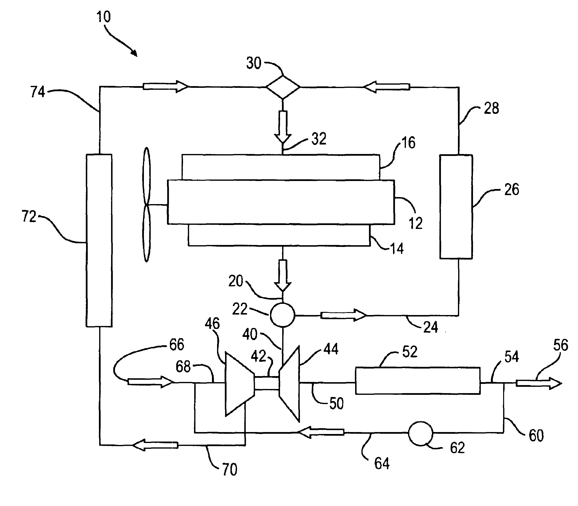
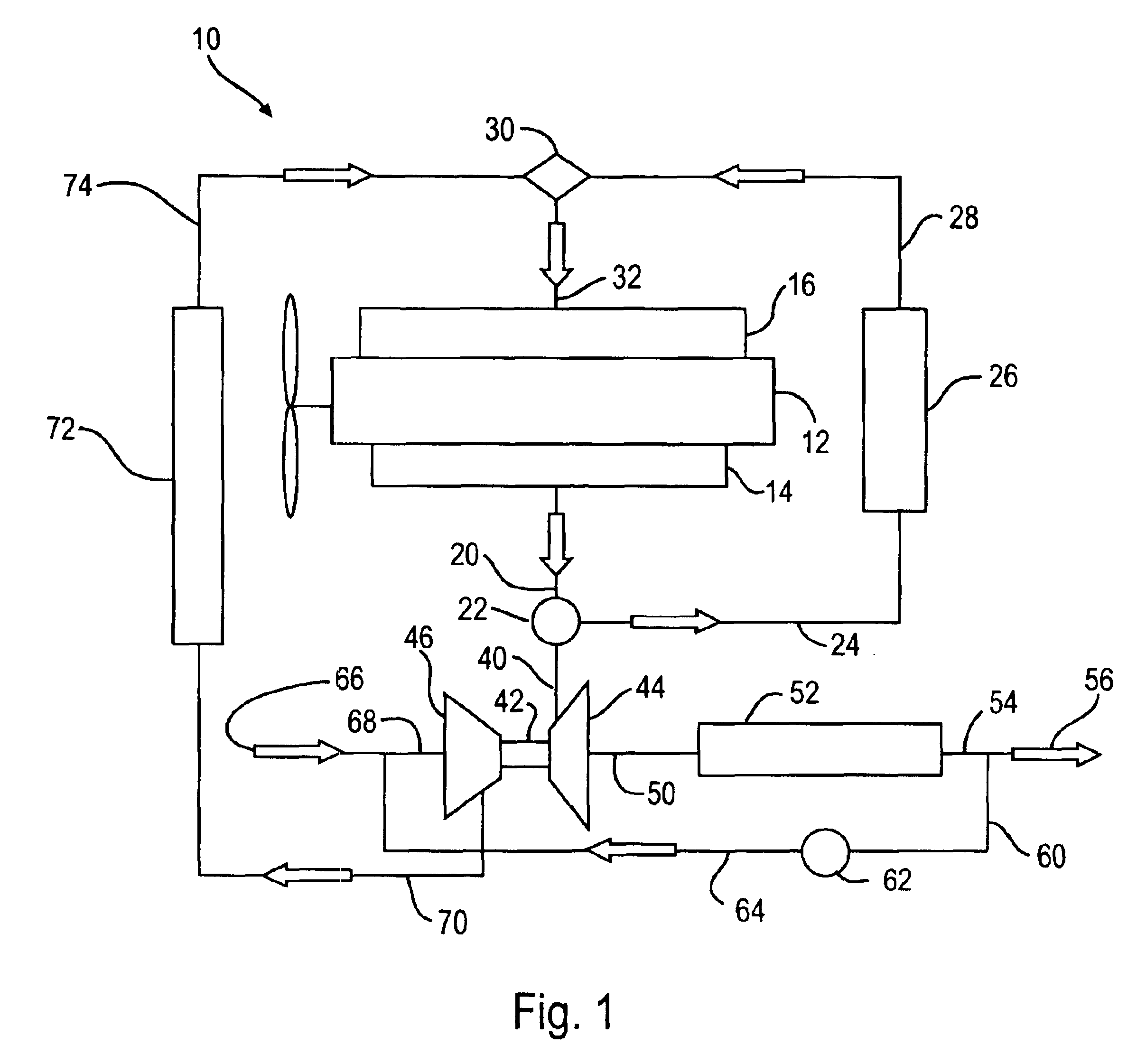
[0017]Referring to the drawings, FIG. 1 shows an internal combustion engine system 10 including the dual path EGR system of this invention. Internal combustion engine 12 has at least one cylinder in communication with exhaust manifold 14 and intake manifold 16. Exhaust manifold 14 is connected to exhaust line 20 which in turn is connected to first control valve 22, which controls the amount of exhaust gas entering high pressure EGR loop line 24. Preferably, first control valve 22 can be controlled such that the amount of exhaust gas entering line 24 can range from a pre-determined maximum to no exhaust gas. Exhaust line 24 is connected to EGR cooler 26, and high pressure EGR loop line 28 connects the outlet of EGR cooler 26 to a first inlet on EGR mixer 30.

[0018]Exhaust gas not diverted to high pressure EGR loop line 24 by first control valve 22 is directed by means of exhaust turbine inlet line 40 to exhaust turbine 44, which exhaust turbine 44 forms a part of turbocharger 42. Exha...


PUM


Abstract

An internal combustion engine system, dual loop EGR system and method is provided, with a high pressure EGR loop, controlled by a control valve, in fluidic connection with the exhaust outlet of the exhaust manifold and the air inlet of the intake manifold, and a low pressure EGR loop, wherein exhaust, in proportions controlled by a control valve, enters a compressor from a point downstream of an exhaust emissions controller, together with fresh air, the low pressure EGR loop being in fluidic connection with an output of the compressor and the air inlet of the intake manifold.

Description

CROSS-REFERENCE TO RELATED APPLICATIONS[0001]This application claims the benefit of the filing of U.S. Provisional Patent Application Ser. No. 60 / 404,955, entitled “Dual EGR Concept”, filed on Aug. 21, 2002, and the specification thereof is incorporated herein by reference.BACKGROUND OF THE INVENTION[0002]1. Field of the Invention (Technical Field)[0003]The present invention relates to the field of internal combustion engine exhaust gas recirculation (EGR) for emissions improvement and increased operating efficiency, including increased fuel economy. More particularly, the invention provides a system and method for dual path EGR, utilizing a high pressure EGR loop, primarily for use under mid and high load engine conditions, and a low pressure EGR loop, combining turbocharger compressed exhaust gas and fresh air, primarily for use under low load engine conditions.[0004]2. Description of Related Art[0005]EGR is a known method for reducing NOx emissions in internal combustion engines,...

Claims


Application Information

Patent Timeline
Patent Type & Authority Patents(United States)
IPC IPC(8): F02B47/00F02B37/18F02B37/24F02M25/07F02B47/08F02B37/12F02D21/00F02D21/08F02B29/04F02B29/00
CPCF02B37/18F02B37/24F02B47/08F02M25/0709F02M25/0727F02M25/0738F02M25/0707F02B29/0406F02D41/0065Y02T10/144Y02T10/121F02M26/05F02M26/06F02M26/23F02M26/33Y02T10/12
Inventor ARNOLD, STEVEN DON
Owner GARRETT TRANSPORATION I INC
Why Eureka
Try Eureka