
Tube for pumping a space between two tiles, especially for a plasma display

a plasma display and spacer technology, applied in the field of tubes, can solve the problems of more difficult to precisely handle glass parts, in general more difficult to position glass pumping tubes at orifices, etc., to facilitate glass-to-metal sealing, facilitate glass-to-metal sealing, and improve the effect of impact resistan

Inactive Publication Date: 2005-05-31
THOMSON LICENSING SA
View PDF11 Cites 2 Cited by
  • Summary
  • Abstract
  • Description
  • Claims
  • Application Information

AI Technical Summary

Benefits of technology

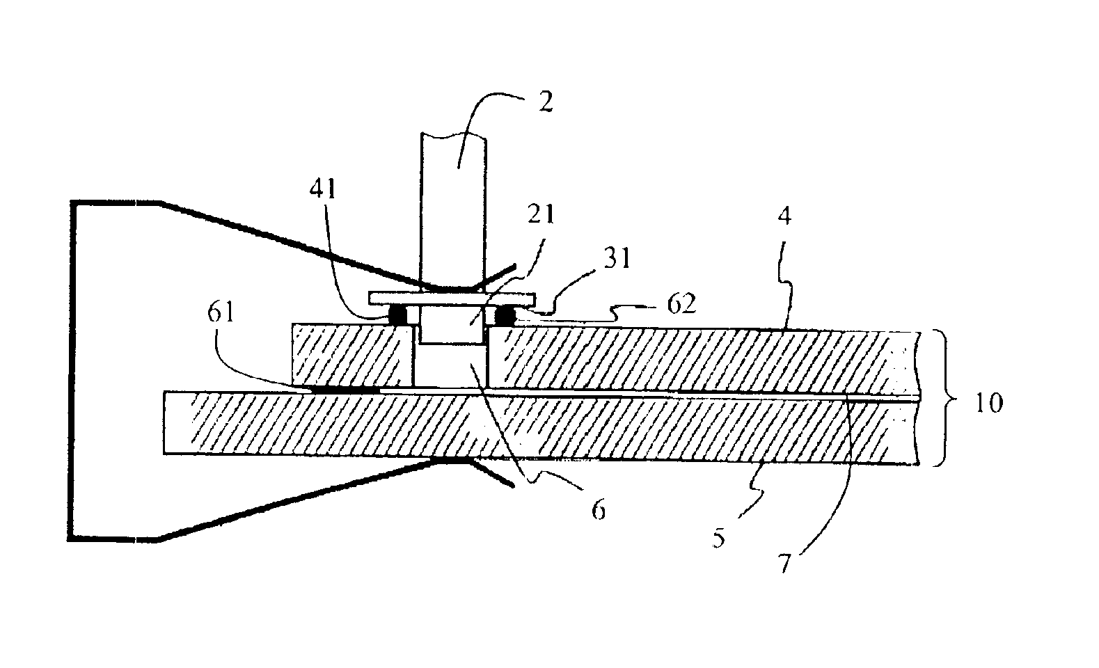
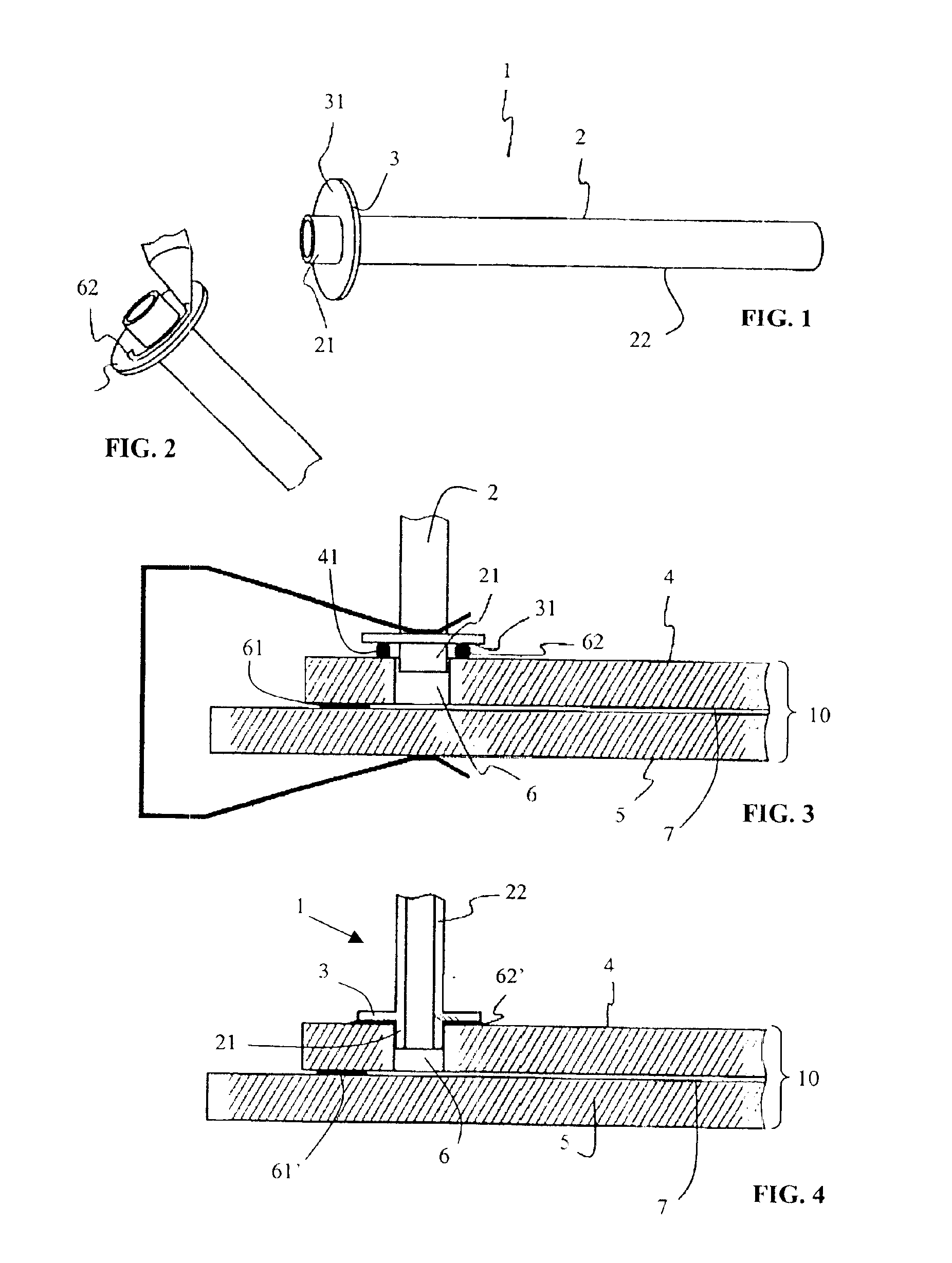
[0029]Such a pumping tube combines the advantages of ease of sealing, thanks to its downstream glass portion, and ease of precise automatic handling and positioning, thanks to its shoulder means and to its upstream metal part; such a pumping tube is particularly inexpensive.
[0030]As the upstream portion of the pipe forms with the shoulder means a metal end-piece, all the metal components of the tube may be produced as a single part, this being particularly inexpensive.
[0038]Preferably, level with the said glass-to-metal seal, the cross section of the cylindrical wall of the upstream portion of the pipe in contact with the glass is chamfered; this chamfer in the thickness of the cylindrical wall means for example that the end of the cylinder is not cut with straight edges; advantageously, this chamfer facilitates the glass-to-metal sealing and makes the bond more impact resistant.
[0039]When the metal part of the tube is produced by punching or drawing, when the shoulder means comprise a single metal plate onto which a glass end of the downstream portion of the pipe is bonded and when the circular edges of the hole in the metal plate extend upstream of the shoulder means, the said metal plate preferably has a convex circular groove, one of the flanks of which is located level with the glass-to-metal seal, thus forming a chamfer which advantageously facilitates the glass-to-metal sealing and makes the bond more impact resistant; it is recommended to avoid a concave or “recessed” groove which would run the risk of trapping air bubbles when making the glass-to-metal seal.

Problems solved by technology

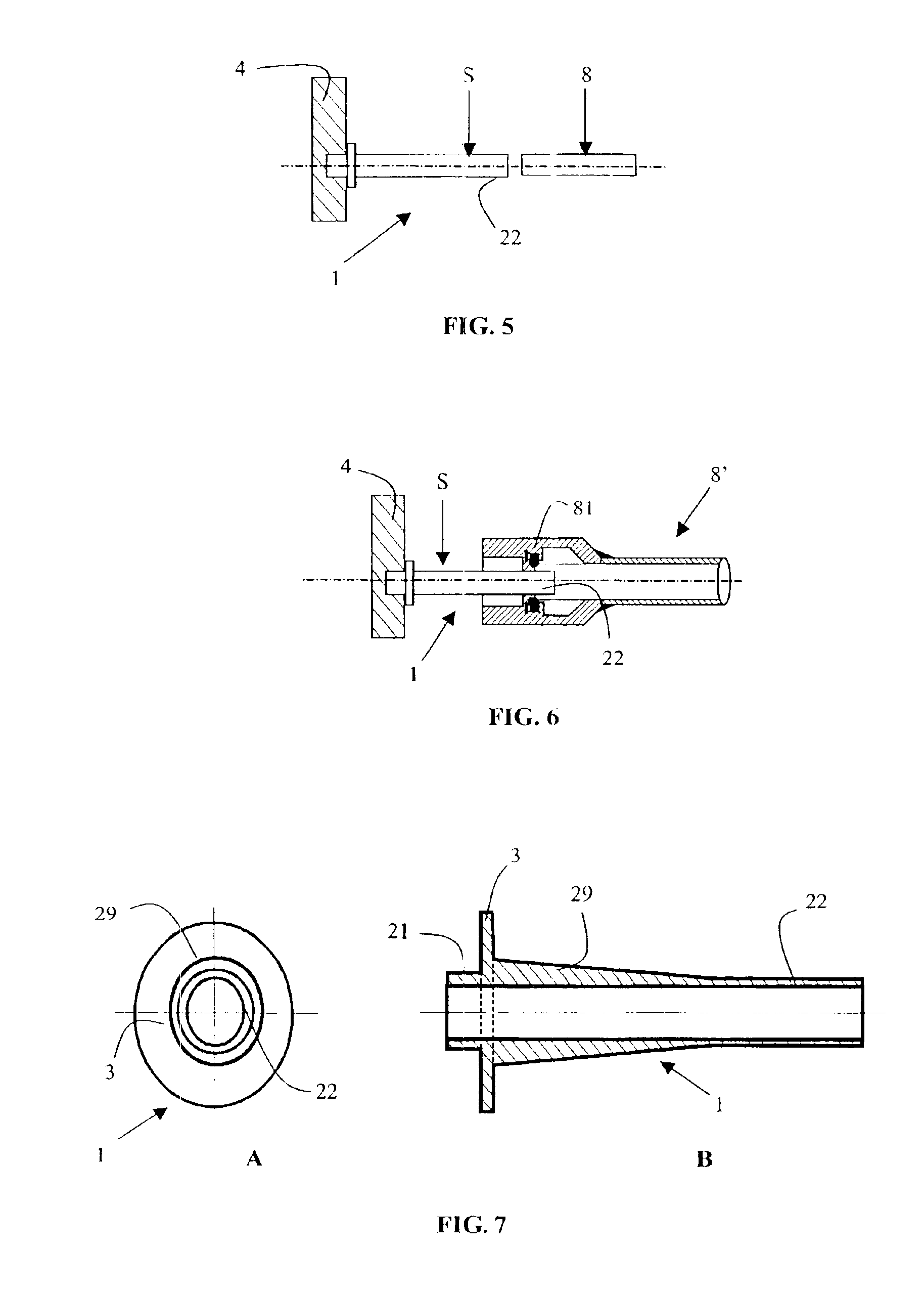
However, a glass pumping tube is in general more difficult to position correctly at the orifice 6 by means of automatic machines; this is because the tolerances at the end 21 and at the shoulder 3 on the tile's 4 side may, if the material is glass, pose a problem in positioning it rapidly and effectively.
Moreover, a glass part is always tricky to handle with automatic machines; in the case of a moulded glass pumping tube, like that shown in FIG. 7, this part generally has a conical outer surface 29 in order to facilitate moulding, which makes it even more difficult to handle precisely.

Method used


Image

  • Tube for pumping a space between two tiles, especially for a plasma display
  • Tube for pumping a space between two tiles, especially for a plasma display
  • Tube for pumping a space between two tiles, especially for a plasma display

Examples


Embodiment Construction

[0051]To simplify the description and bring out the differences and advantages that the invention has over the prior state of the art, identical reference numbers will be used for the elements which fulfil the same functions.

[0052]According to a preferred embodiment shown in FIG. 8, the tube 1′ according to the invention comprises a cylindrical pumping pipe 2 and metal shoulder means 3; the cylindrical pumping pipe 2 has a metal upstream portion 24 with its end 21 for fitting into a pumping orifice and a glass downstream portion 25, the two portions being bonded together by a glass-to-metal seal 26; the shoulder means 3 and the metal upstream portion 24 of the pipe 2 form a single metal part, namely the end-piece 9; thus, the pumping tube is also described as comprising a metal end-piece 9 and a glass tube 25, bonded together with a glass-to-metal seal 26, the metal end-piece 9 having shoulder means 3.

[0053]The metal end-piece 9 makes it easier for the pumping tube to be handled, po...


PUM


Abstract

Tube for pumping a space between two tiles, comprising a metal end-piece 9 and a glass tube 25 bonded together via a glass-to-metal seal 26; the metal end-piece 9 has shoulder means 3. Such a tube is especially intended to be fitted onto plasma displays or field emission displays.This tube is inexpensive and allows rapid and precise handling and fitting.

Description

FIELD OF THE INVENTION[0001]Referring to FIGS. 1 to 4, the invention relates to a tube 1 for pumping, where appropriate for filling, and for sealing, a space 7 between two flat tiles 4 and 5; this tube 1 comprises a cylindrical pumping pipe 2 one end 21 of which is intended to be fitted into a pumping orifice 6 made in one of the tiles 4 and communicating with the space 7 between the tiles; for this purpose, the outside diameter of the tubular pipe 2 is, at this end 21, less or slightly less than the diameter of the pumping orifice 6; the other end 22 of the tube is intended to be connected to pumping, and where appropriate filling, means; the two flat tiles together form a panel that can be used, for example, for the production of a plasma panel for display or addressing or for the production of a field emission display.BACKGROUND ART[0002]A plasma display generally comprises two tiles, leaving between them a space filled with a discharge gas, and at least two arrays of electrodes ...

Claims


Application Information

Patent Timeline
Patent Type & Authority Patents(United States)
IPC IPC(8): H01J7/22H01J9/385H01J9/38H01J7/00H01J5/22H01J17/49H01J11/02
CPCH01J7/22H01J9/385Y10S285/911H01J9/24H01J11/34
Inventor NORMANNI, ALAIN
Owner THOMSON LICENSING SA
Learn More