Current driving type emissive display apparatus, method for driving the same and method for producing the same

a display apparatus and current driving technology, applied in static indicating devices, instruments, organic semiconductor devices, etc., can solve the problems of deterioration of thin-film transistors over time, device operating under more complex voltage and current relationships, and the apparatus with thin-film transistors is not as simple, so as to reduce the deterioration of the second switching element, improve the luminous efficiency, and reduce power consumption.

Inactive Publication Date: 2005-05-31
SEIKO EPSON CORP
View PDF21 Cites 33 Cited by
  • Summary
  • Abstract
  • Description
  • Claims
  • Application Information

AI Technical Summary

Benefits of technology

[0036]This configuration can realize a reduction in the deterioration of the second switching element over time due to a DC voltage or a direct current, and also improvement of the luminous efficiency and reduction in the power consumption by permitting a luminescent element to emit light during both periods of inversion of the potential between the first feeder and the second feeder, without an additional producing process.

Problems solved by technology

The actual operation of organic EL display apparatuses with thin-film transistors is not as simple as that described above and the devices operate under more complex relationships of voltages and currents.
However, when a DC voltage is applied not only to the organic EL device but also to the thin-film transistor or a direct current flows, a rapid deterioration of the thin-film transistor over time will be caused.
Thus it requires an increase in power consumption to obtain the same amount of light emission as in the case in which a DC voltage is applied to cause a direct current to flow.

Method used


Image

  • Current driving type emissive display apparatus, method for driving the same and method for producing the same
  • Current driving type emissive display apparatus, method for driving the same and method for producing the same
  • Current driving type emissive display apparatus, method for driving the same and method for producing the same

Examples


first embodiment

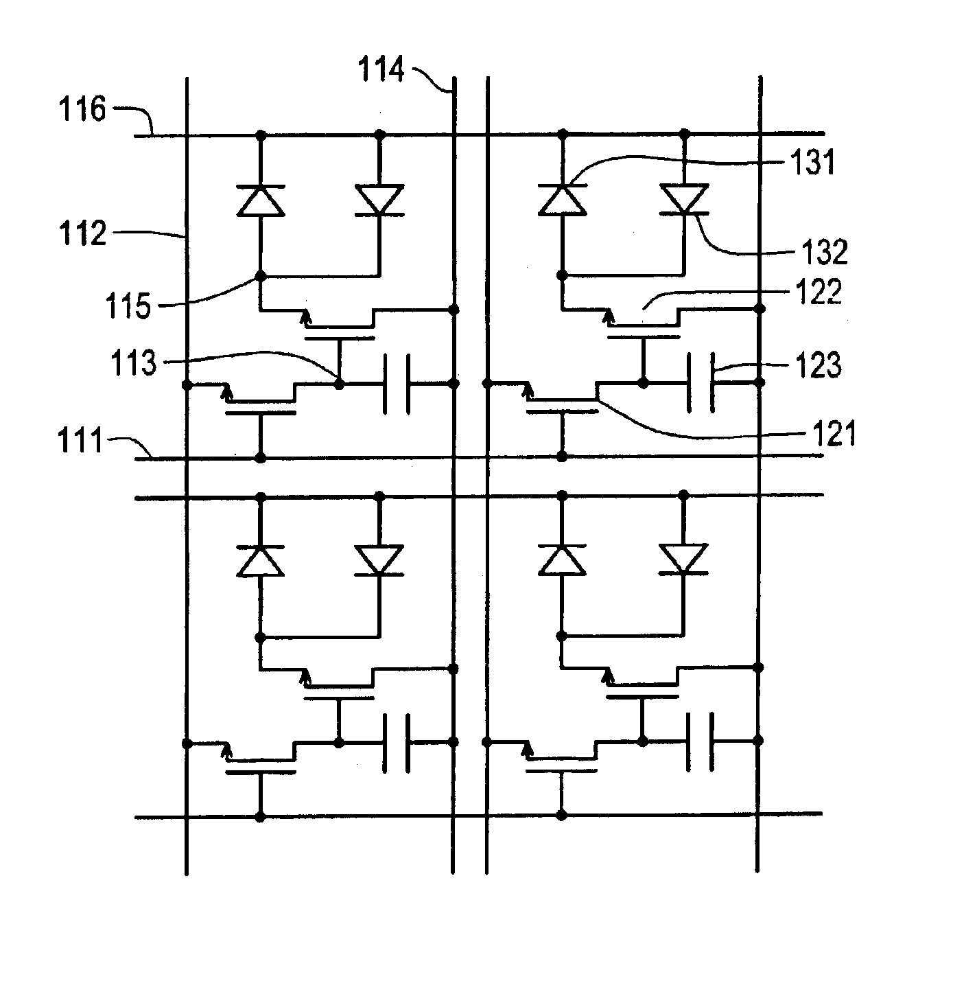
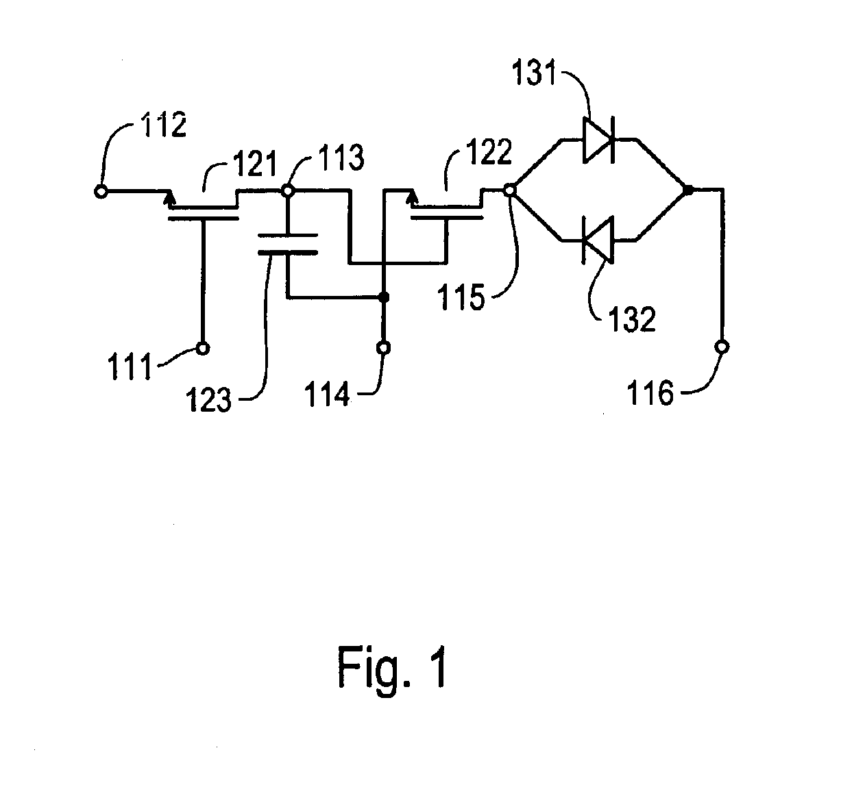
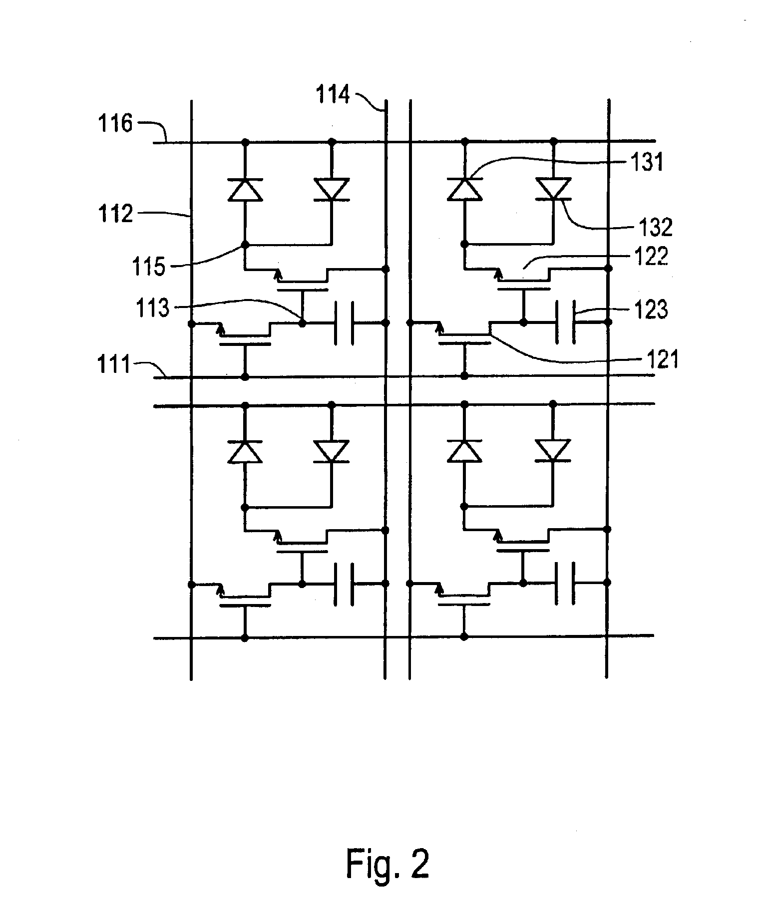
[0058]FIG. 1 is an equivalent circuit diagram of one pixel of an organic EL display device having a thin-film transistor according to a first embodiment of this invention, FIG. 2 is an equivalent circuit diagram showing the matrix construction of an organic EL display device equipped with a thin-film transistor according to the first embodiment of this invention, and FIG. 3 is a driving voltage diagram of an organic EL display device having a thin-film transistor according to the first embodiment of this invention.

[0059]The operation of the organic EL display device having the thin-film transistor of this embodiment will be described with reference to FIGS. 1, 2, and 3.

[0060]As shown in FIGS. 1 and 2, a data line 112 is formed so as to extend perpendicular to the direction of a scanning line 111. The scanning line 111 is connected to a gate electrode of a first switching element (hereinafter referred to as a “switching thin-film transistor”), and one of a source or a drain of the sw...

second embodiment

(Second Embodiment)

[0070]FIG. 6 is an equivalent circuit diagram of one pixel of an organic EL display device having a thin-film transistor of a second embodiment of this invention, FIG. 7 is an equivalent circuit diagram showing the matrix construction of the organic EL display device equipped with the thin-film transistor according to the second embodiment of the invention, and FIG. 8 is a driving voltage diagram of the organic EL display device having the thin-film transistor of the second embodiment of this invention.

[0071]The operation of the organic EL display device having a thin-film transistor of this embodiment will be described with reference to FIGS. 6, 7, and 8. Since the construction of this embodiment is similar to that of the first embodiment, only those points which differ from the first embodiment will be explained.

[0072]The switching thin-film transistor 121, the storage capacitor 123, and the current thin-film transistor 122 operate in the same way as in the firs...

third embodiment

(Third Embodiment)

[0080]FIG. 11 is an equivalent circuit diagram of one pixel of an organic EL display device having a thin-film transistor of a third embodiment of this invention, FIG. 12 is an equivalent circuit diagram showing the matrix construction of the organic EL display device having a thin-film transistor of the third embodiment of the invention, and FIG. 13 is a driving voltage diagram of the organic EL display device having a thin-film transistor of the second embodiment of this invention.

[0081]The operation of the organic EL display device having a thin-film transistor of this embodiment will be described with reference to FIGS. 11, 12, and 13. Since the construction of this embodiment is also similar to that of the first embodiment, only those points which differ from the first embodiment will be explained.

[0082]The switching thin-film transistor 121, the storage capacitor 123, and the current thin-film transistor 122 operate in the same way as in the first embodiment....


PUM


Abstract

A reduction in deterioration of a switching element over time in a current driving type emissive apparatus is realized. At the same time, a reduction in power consumption is realized. To this end, an AC voltage or an alternating current is applied between a source and a drain terminal of a switching element, and a DC voltage or a direct current is applied between a first and a second terminal of a luminescent element. This is realized by application of a voltage, which is inverted at predetermined intervals, to two luminescent elements heterogeneously arranged, to a luminescent element and a rectifier arranged in reverse orientation and in parallel, or to a full-wave rectification circuit. At this time, the rectifier is formed by a thin-film transistor, a PN junction, or a PIN junction, and is formed simultaneously with an existing switching element.

Description

[0001]This is a division of application Ser. No. 09 / 171,117 filed Oct. 13, 1998. The entire disclosure of the prior application(s) is hereby incorporated by reference herein in its entirety.BACKGROUND OF THE INVENTION[0002]1. Field of the Invention[0003]The present invention relates to a current driving type emissive display apparatus such as an organic electro luminescence (hereinafter referred to as an “organic EL”) device having a thin-film transistor and a method for driving the apparatus, and more particularly, to a technique for realizing a reduction in deterioration over time or a reduction in both deterioration over time and electric power consumption simultaneously.[0004]2. Description of Related Art[0005]An operation of a conventional current driving type emissive apparatus such as an organic EL having thin-film transistors will be described with reference to FIGS. 16, 17, and 18.[0006]FIG. 16 is an equivalent circuit diagram of one pixel of the conventional organic EL dis...

Claims


Application Information

Patent Timeline
Patent Type & Authority Patents(United States)
IPC IPC(8): G09G3/32H01L27/32H01L27/28H01L21/77H01L33/26H05B44/00
CPCG09G3/3233G09G2300/0842G09G2310/0254G09G2310/0256H01L2251/564H01L27/1214H01L27/3244H01L27/3262G09G2320/043H01L27/1255H10K59/12H10K59/1213H10K71/841G09G3/30
Inventor KIMURA, MUTSUMI
Owner SEIKO EPSON CORP
Why Eureka
Try Eureka