X-ray computer tomography apparatus

Inactive Publication Date: 2005-05-31
TOSHIBA MEDICAL SYST CORP
View PDF8 Cites 24 Cited by
  • Summary
  • Abstract
  • Description
  • Claims
  • Application Information

AI Technical Summary

Benefits of technology

[0023]FIG. 2 is a graph showing the relationship between the angular position of an X-ray tu

Problems solved by technology

It may safely be said that such progress in X-ray CT apparatuses is the result of relentless challenges to an improvement in image quality, reductions in imaging time and image reconstruction time, a reduction in X-ray dose, and the like.
In this case, however, an excessive amount of X-rays is applied to a portion originally having a high S/N ratio.

Method used


Image

  • X-ray computer tomography apparatus
  • X-ray computer tomography apparatus
  • X-ray computer tomography apparatus

Examples


first embodiment

(First Embodiment)

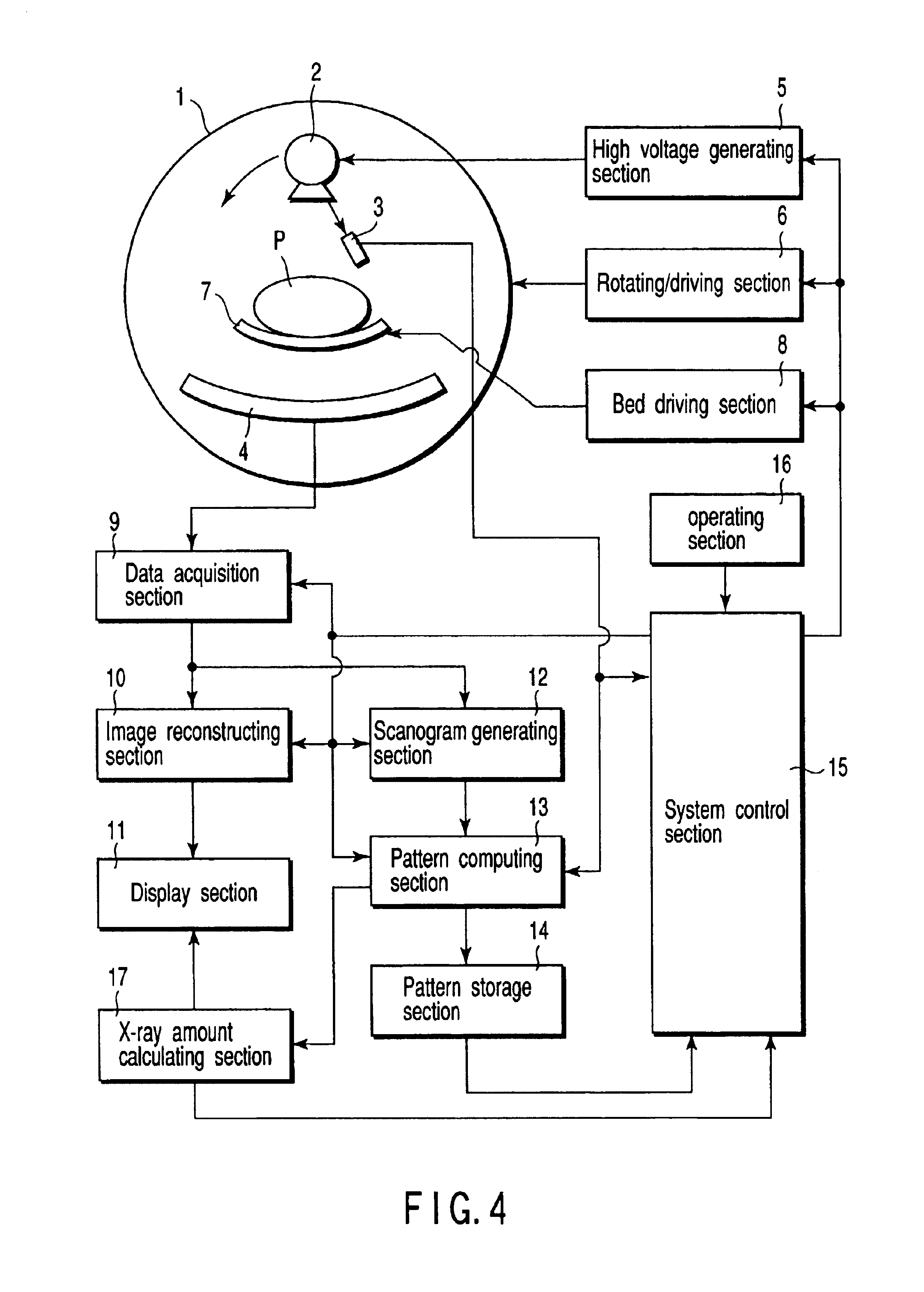
[0033]FIGS. 4 and 5 are views showing the schematic arrangement of an X-ray CT apparatus according to the first embodiment. FIG. 4 is a front view of a gantry 1. FIG. 5 is a side view of the gantry 1.

[0034]As shown in FIGS. 4 and 5, the X-ray CT apparatus according to this embodiment includes the gantry 1, an X-ray tube 2, a compensatory detector 3, an X-ray detector 4, a high voltage generating section 5, a rotating / driving section 6, a bed 7, a bed driving section 8, a data acquisition section 9, an image reconstructing section 10, a display section 11, a scanogram generating section 12, a pattern computing section 13, a pattern storage section 14, a system control section 15, and an operating section 16.

[0035]The gantry 1 has a rotating ring. The rotating ring has the X-ray tube 2, compensatory detector 3, and X-ray detector 4. This rotating ring is rotated / driven by the rotating / driving section 6.

[0036]The X-ray tube 2 is a vacuum tube for generating X-rays and...

second embodiment

(Second Embodiment)

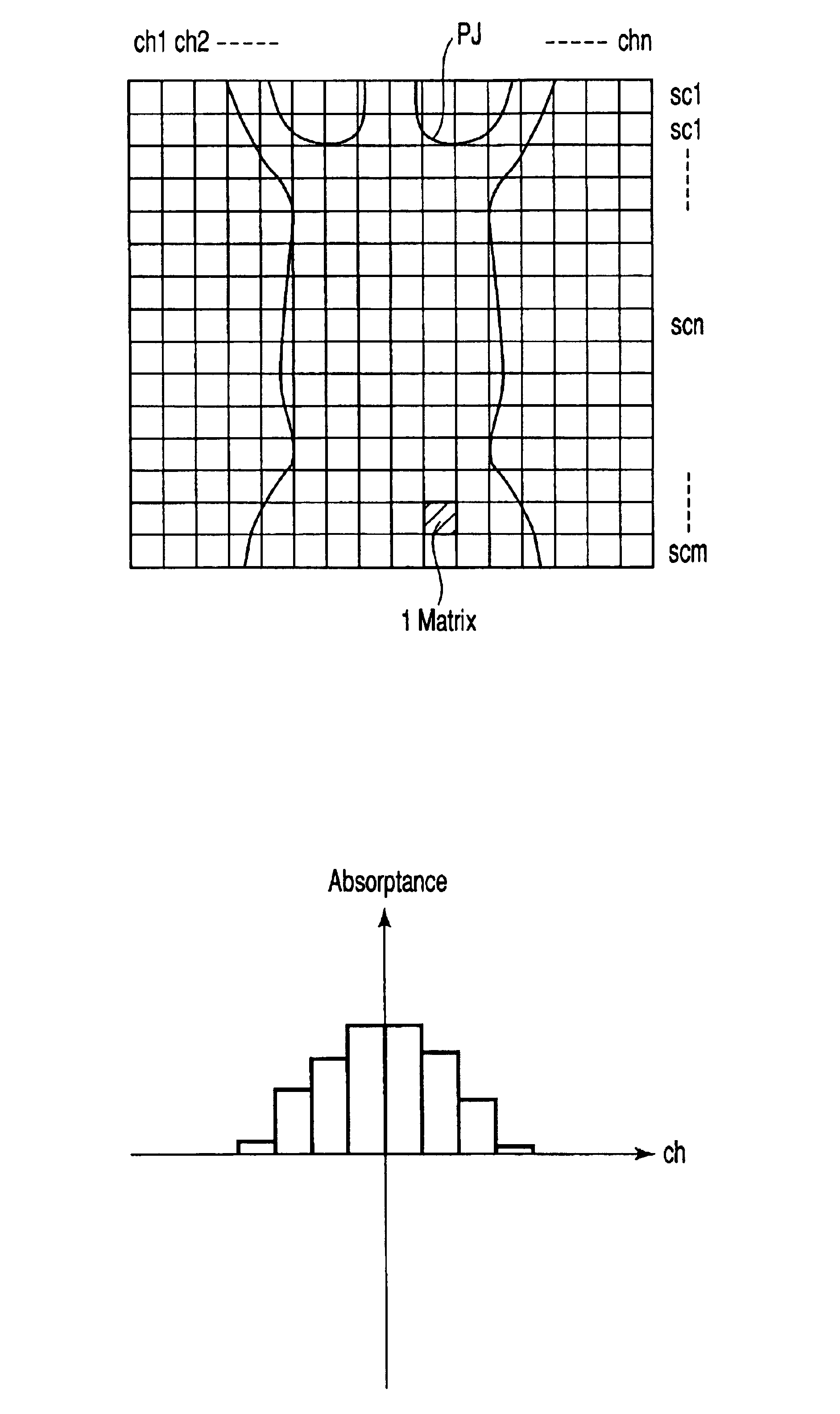
[0091]An X-ray CT apparatus according to the second embodiment will be described next. The X-ray CT apparatus according to this embodiment is designed to determine the size of a object P to be examined on the basis of a scanogram formed before tomography and adjust the amount of X-rays emitted in tomography in accordance with the size of the object. For the sake of a specific description, this embodiment will exemplify a case wherein whether the object P is a child or not is determined on the basis of an absorptance map obtained from a scanogram, and the amount of X-ray emitted in tomography is adjusted in accordance with the determination. However, the present invention is not limited to this. For example, an object size can be directly determined on the basis of the CT values from the respective detection elements, which form a scanogram, and the amount of X-rays emitted in tomography can be adjusted in accordance with the size.

[0092]The arrangement of the X-ray...


PUM


Abstract

An X-ray absorptance map associated with an object to be examined is generated on the basis of scanogram data obtained from a predetermined direction of the object, and imaging conditions are determined on the basis of the absorptance map. Before tomography, an index representing a radiation dose in the execution of scan in accordance with the imaging conditions is calculated and displayed, together with the imaging conditions. Every time the imaging conditions are changed, an index representing a radiation dose is calculated and displayed. Tomography is executed in accordance with the finally determined imaging conditions. This makes it possible to reduce the radiation dose to the object and obtain a tomographic image with high quality.

Description

CROSS-REFERENCE TO RELATED APPLICATIONS[0001]This application is based upon and claims the benefit of priority from the prior Japanese Patent Application No. 2001-202870, filed Jul. 4, 2001, the entire contents of which are incorporated herein by reference.BACKGROUND OF THE INVENTION[0002]1. Field of the Invention[0003]The present invention relates to an X-ray computer tomography apparatus which dynamically changes an imaging condition during a scan on the basis of the scanogram data obtained by scanography executed before the start of the scan.[0004]2. Description of the Related Art[0005]X-ray computer tomography apparatuses (to be referred to as “X-ray CT apparatuses” hereinafter) have made remarkable progress after they were invented. Recently, X-ray CT apparatuses have been put into practice, which allow imaging schemes such as helical scan in which an object to be examined is helically irradiated with X-rays by helically and continuously rotating an X-ray tube while moving an o...

Claims


Application Information

Patent Timeline
IPC IPC(8): A61B6/03G01N23/04G01N23/02G06F19/00G16H30/20G16H30/40
CPCA61B6/032A61B6/488A61B6/542A61B6/544G01N23/046A61B6/583G06F19/3406G06F19/321G01N2223/612A61B6/027Y10S378/901A61B6/507G01N2223/419G16H40/63G16H30/20G16H30/40
Inventor TACHIZAKI, HISASHIKAZAMA, MASAHIRO
Owner TOSHIBA MEDICAL SYST CORP
Why Eureka
Try Eureka