Eureka AIR delivers breakthrough ideas for toughest innovation challenges, trusted by R&D personnel around the world.

Solar collector comprising an opaque cover

a solar collector and opaque cover technology, applied in the field of solar collectors, can solve the problems of poor edge strength, high cost of shipping, and difficult handling of flat-plate solar collectors, and achieve the effects of high solar energy absorption and high infrared emittan

Active Publication Date: 2014-10-16
PRUTSMAN JEFFREY D +1
View PDF5 Cites 14 Cited by
  • Summary
  • Abstract
  • Description
  • Claims
  • Application Information

AI Technical Summary

Benefits of technology

The present invention is a solar collector with an opaque cover that converts solar energy to heat. The opaque cover has high solar energy absorptance and low infrared emittance, while the interior surface is hotter than the absorber surface. The continuous side wall of the solar collector has rounded corners that reduce windload stresses and convective heat loss. The hollow portion of the continuous side wall can be filled with air or insulation to further reduce convective heat loss. Evacuating the solar collector interior virtually eliminates convective heat losses. These features make the solar collector more efficient and durable.

Problems solved by technology

The use of glass makes flat plate solar collectors difficult to handle and expensive to ship.
Also, tempered glass is not impervious to breakage.
While tempering produces excellent flat surface impact resistance, the edge strength is poor.
Unfortunately, these materials suffer significant reductions in transmittance over time due to discoloration and structural degradation, caused by accumulated exposure to ultraviolet radiation and stagnation temperatures.
Plastic glazing materials also tend to experience unacceptable levels of outward bowing when exposed to the dynamic pressures associated with severe windstorms.
An additional problem for both transparent and translucent cover plate materials is that airborne dust and grime can accumulate on the glazing surface, which reduces solar energy transmittance.
In many climates, the frequency and intensity of rainfall are not sufficient to remove accumulated dust and grime.
Further, it is a practical reality that periodic manual glass cleaning is problematic for solar collectors on residential rooftops and in large commercial arrays.
First, the solar collector side walls expand and contract with daily temperature variations.
Over time, repeated expansion and contraction can lead to small gaps at the corner joints.
This problem may be exacerbated by a difference in the upper horizontal side wall and the lower horizontal side wall temperatures, leading to small but meaningful differences in the longitudinal expansion and contraction of the upper and lower horizontal side walls.
With even the smallest corner gaps, moisture and particulate laden air infiltration into the solar collector interior will inevitably occur, urged by pressure differences between the air inside the solar collector and ambient air.
The lack of effective corner sealing is due in part to the practical difficulty of sealing the abrupt, planar and pointed surface intersections at the top and bottom of each corner joint.
While the corner joints could be welded, this strategy imposes unacceptable labor costs and is incompatible with the most common frame material and finish, which comprises an anodized finish of an aluminum frame.
A problem closely related to the wind uplift pressure issue discussed above is that any structure comprising a blunt windward edge with square corners promotes formation and shedding of vortex currents along the edges disposed downwind from such corners.
If the frequency of the vortex shedding happens to match the resonance frequency of the structure, the structure will begin to resonate and the structure's movement can become self-sustaining Vortex shedding on a solar collector perimeter during a severe windstorm can literally shake roof shingles loose and start progressive undermining of the entire roof structure, leading to eventual catastrophic loss.
Roof deck failure is the leading cause of catastrophic residential building damage during severe windstorms.
Once a building loses one or more pieces of roof deck, damage increases exponentially as vast amounts of wind-driven water enter the structure.
Insurance claim data show that damage escalates quickly once a roof deck starts to fail.
Even if the walls remain intact and the roof trusses do not fail, loss of the roof deck typically results in losses greater than 50% of building insured value.
While such glass cylinders do have a degree of impact resistance, breakage can nevertheless occur as a result of impacts by hail, wind-driven storm debris, errant golf balls and baseballs, and dropped tools.
Breakage can also occur during shipping and handling.
Snow accumulation is also a problem for evacuated tube collectors.
However, the glass of an evacuated tube solar collector is only warmed by the small percentage of incident solar energy absorbed by the glass, and this heat is quickly lost to the cold ambient air that accompanies a snowfall.
Thus, absent manual snow removal, evacuated tube solar collectors are rendered useless for some period of time after a snowfall.
However, the Dalstein '241, Benvenuti '491 and Palmieri '965 patents do not solve the problems associated with flat plate solar collector glazing or sharp side wall corners, or the problem of snow accumulation on the outer glass surface of an evacuated solar collector.
Unfortunately, though, unglazed solar collectors suffer much greater convective heat losses than glazed flat plate solar collectors when the ambient air temperature falls below the solar collector fluid inlet temperature.
Poor cold weather performance is acceptable for solar swimming pool heating because the goal in most climates is only to extend the swimming season by a few extra months.

Method used


Image

  • Solar collector comprising an opaque cover
  • Solar collector comprising an opaque cover
  • Solar collector comprising an opaque cover

Examples


Embodiment Construction

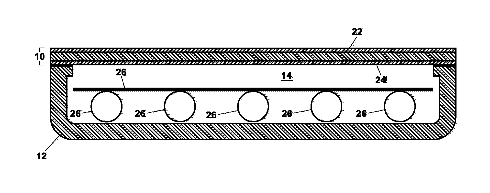
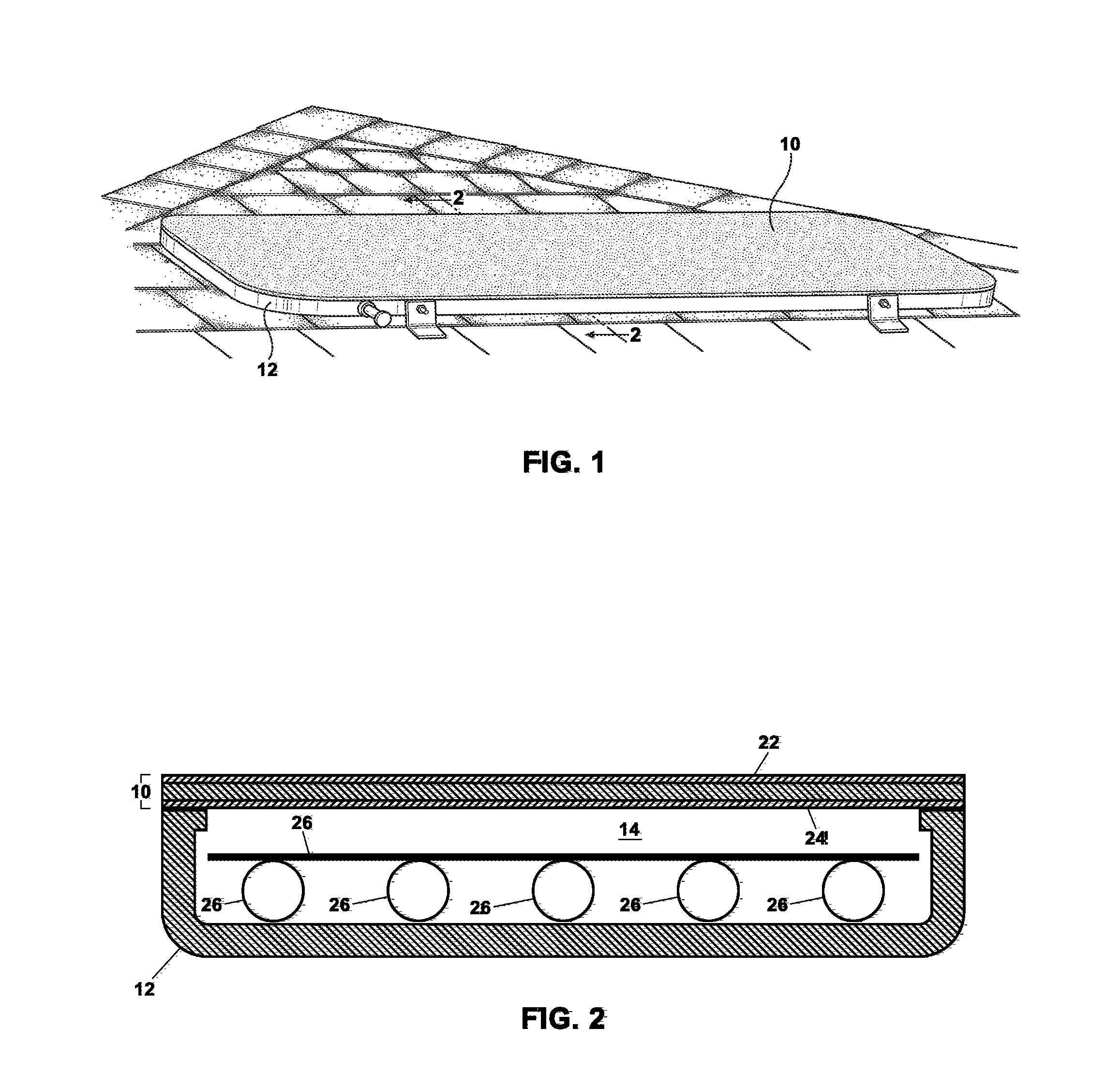
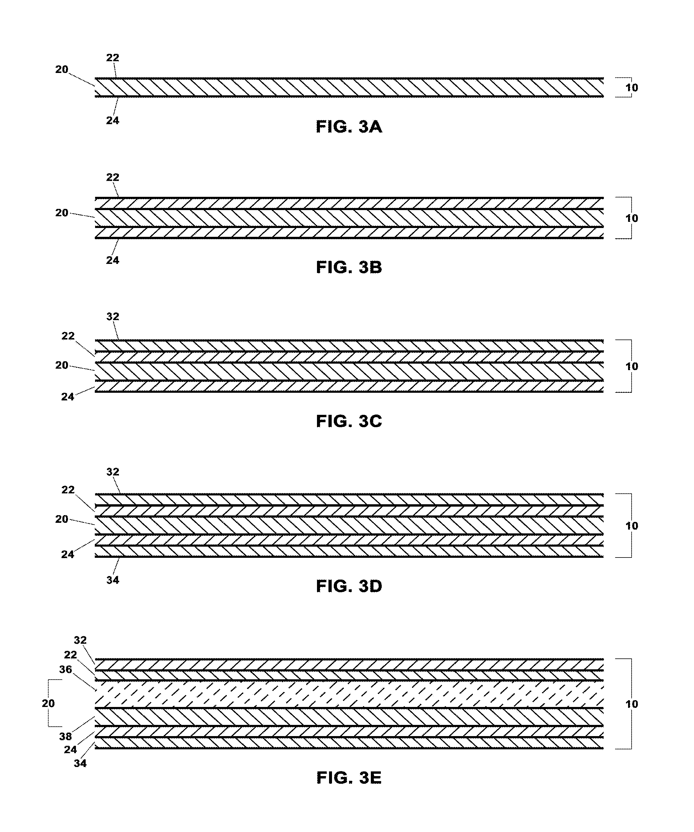
[0031]Turning now to FIG. 1, the present invention is directed to a solar collector comprising an opaque cover 10 disposed to receive incident solar energy and coupled to an upper portion of a housing 12. A cross-sectional view of one embodiment, taken at section line 2-2 of FIG. 1, is illustrated in FIG. 2. The opaque cover 10 preferably comprises a planar structure but can also be dome-shaped, corrugated, or any other shape suitable for receiving incident solar energy and providing for structural integrity under anticipated loads. The housing 12 may be of any shape and construction suitable to isolate an absorber 26 from ambient air, provided that coupling of the opaque cover 10 to an upper portion of the housing 12 defines an at least substantially airtight enclosure 14. The absorber 26 is disposed within the enclosure 14 in an opposing spaced apart relationship with the opaque cover 10.

[0032]The present invention is directed to a solar collector that operates by a fundamentally ...


PUM

PropertyMeasurementUnit
radiusaaaaaaaaaa
pressureaaaaaaaaaa
temperaturesaaaaaaaaaa

Abstract

A solar collector has an opaque cover heated by solar energy. Heat flows from the opaque cover by conduction, convection, and infrared emittance across a gap within an at least substantially airtight enclosure to an absorber containing a working fluid. The exterior surface of the opaque cover has high solar energy absorptance and the interior surface has high infrared emittance. The exterior surface preferably has low infrared emittance. In one embodiment, fully wetted surface geometry permits direct and reflected infrared absorption by the absorber. The opaque cover eliminates the weight, cost and other shortcomings of glass. A hollow continuous side wall with rounded corners provides an embodiment that is robust yet economical, that is easy to manufacture and seal, that permits a reduced thickness of the opaque cover and mitigates the destructive potential of severe winds, and that can withstand the compressive forces experienced by an evacuated solar collector.

Description

CROSS-REFERENCE TO RELATED APPLICATIONS[0001]This application claims priority to and the benefit of U.S. Provisional Application Ser. No. 61 / 811,495, filed on Apr. 12, 2013.STATEMENT REGARDING FEDERALLY SPONSORED RESEARCH OR DEVELOPMENT[0002]Not ApplicableTHE NAMES OF THE PARTIES TO A JOINT RESEARCH AGREEMENT[0003]Not ApplicableREFERENCE TO A SEQUENCE LISTING, A TABLE, OR A COMPUTER PROGRAM, LISTING COMPACT DISC APPENDIX[0004]Not ApplicableBACKGROUND OF THE INVENTION[0005]1. Field of the Invention[0006]The present invention relates to solar collectors, and more particularly to solar thermal collectors designed to heat a working fluid to temperatures within a range of about 25° C. to 180° C.[0007]2. Description of Related Art[0008]The flat plate solar collector has not fundamentally changed since the 1970s. U.S. Pat. No. 4,011,856 to Gallagher (1977) teaches an exemplary design that fairly represents the vast majority of glazed flat plate solar collectors in use today. Such solar col...

Claims


Application Information

Patent Timeline
Patent Type & Authority Applications(United States)
IPC IPC(8): F24J2/05F24J2/32F24J2/50F24J2/24F24J2/48F24S10/40F24S10/70F24S10/95F24S23/70
CPCF24J2/05F24J2/24F24J2/32F24J2/505F24J2/485F24S10/73F24S10/742F24S10/748F24S10/95F24S25/20F24S70/14F24S70/225F24S70/30F24S80/453F24S80/457F24S80/52F24S80/56F24S80/60F24S2023/84F24S2023/86F24S2025/011Y02B10/20Y02E10/44Y02E10/47
Inventor PRUTSMAN, JEFFREY D.PRUTSMAN, JOHN D.
Owner PRUTSMAN JEFFREY D
Why Eureka
Eureka Blog
Learn More