Legged mobile robot and control method thereof, leg structure of legged mobile robot, and mobile leg unit for legged mobile robot

Inactive Publication Date: 2005-05-31
SONY CORP
View PDF30 Cites 44 Cited by
  • Summary
  • Abstract
  • Description
  • Claims
  • Application Information

AI Technical Summary

Benefits of technology

[0104]In the legged job, the robot dynamically generates the ZMP behavior space having a space distortion

Problems solved by technology

The legged mobile robot is unstable and presents more difficulty in posture control and legged control than crawling robots, quadrupedalling robots, and sextuple pedalling robots.
The falling means an interruption of the activity of the robot, and a great deal of labor and time is required to stand up from the fallen state and to resume the activity.
There is a risk that the robot itself is damaged and that an object that could be hit by the falling robot may be severely destroyed.
Without adequately managing the momentum of the robot in response to the force exerted on the robot, a space within which the ZMP is present becomes unstable.
As the center of gravity of the robot becomes lower in level, a rotary motion takes place in the robot body, and stable walking becomes very difficult to accomplish.
A typical example of the control method in which the ZMP position is continuously shifted back to the center is an “inverse pendulum.” In this case, high-speed control needs to be carried out (specifically, the sampling period of the system is extremely short), and the workload on a computer performing posture control increases.
The reaction force can become a disturbance, leading to an instability of the robot.
When the robot receives a reaction force from the ground surface during the landing of the le

Method used


Image

  • Legged mobile robot and control method thereof, leg structure of legged mobile robot, and mobile leg unit for legged mobile robot
  • Legged mobile robot and control method thereof, leg structure of legged mobile robot, and mobile leg unit for legged mobile robot
  • Legged mobile robot and control method thereof, leg structure of legged mobile robot, and mobile leg unit for legged mobile robot

Examples


Embodiment Construction

[0157]The embodiments of the present invention are discussed below with reference to the drawings.

A. Construction of the Robot

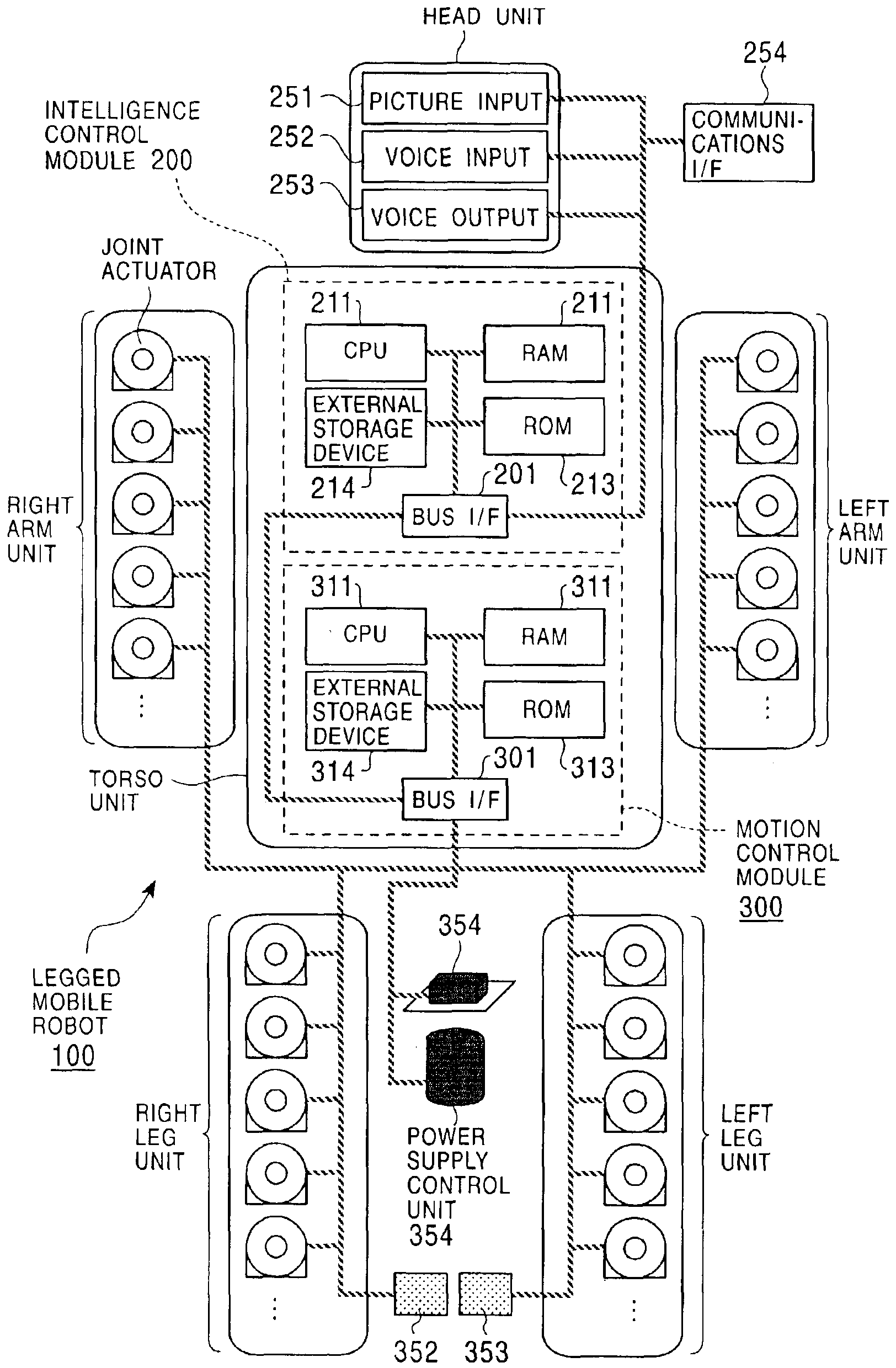
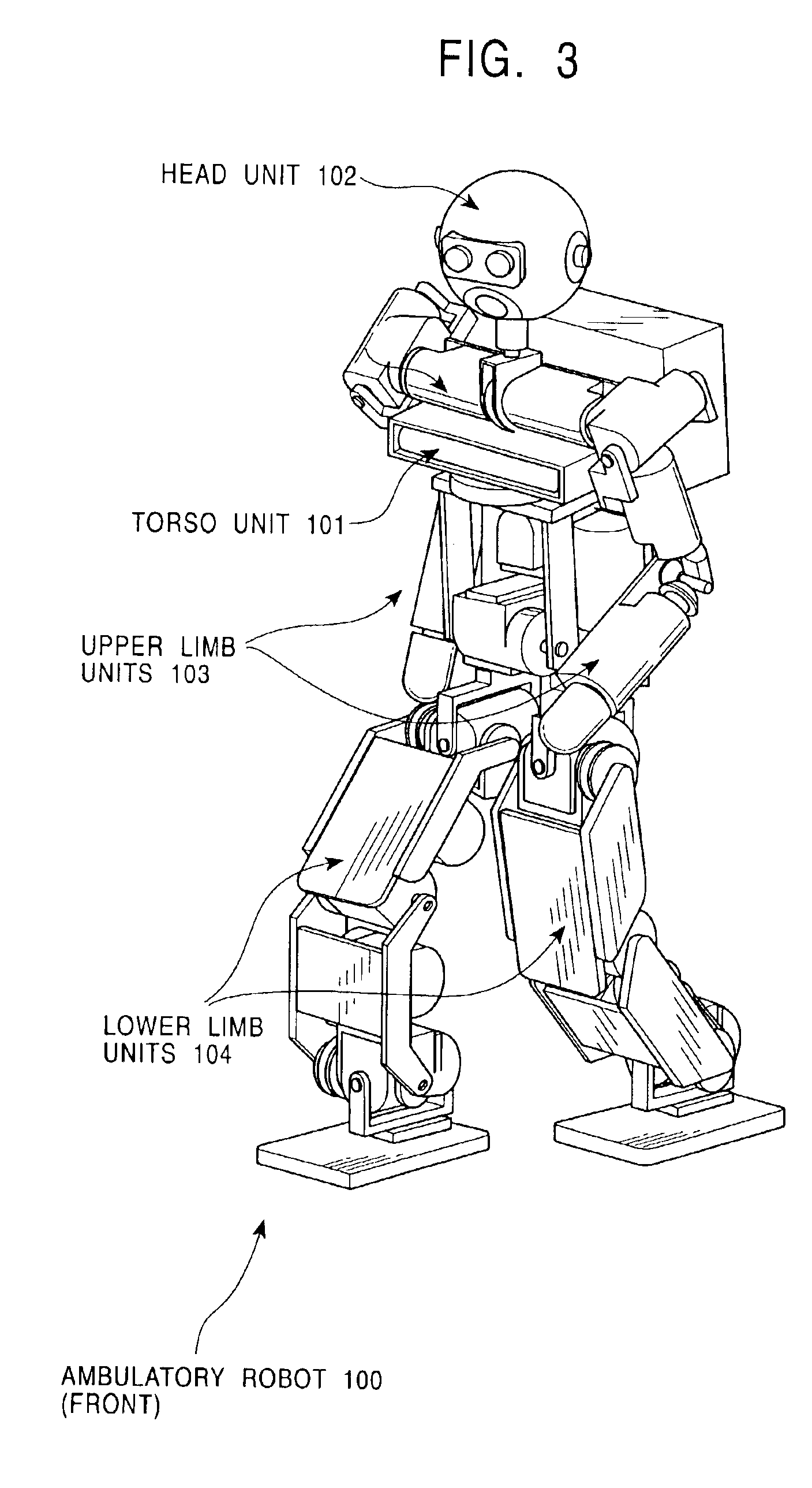
[0158]FIG. 3 and FIG. 4 illustrate the front and back of a “human-like figured” or “human-type” legged mobile robot 100 in an upstanding position, in which the present invention is implemented. As shown, the legged mobile robot 100 includes a torso unit 101, a head unit 102, left and right upper limb units 103, left and right lower limb units 104 for legging, and a controller 105 for generally controlling the operation of the robot body.

[0159]The left and right lower limb units 104, each of which includes a thigh, a knee joint, a lower thigh, an ankle, and a foot, are connected to the approximate lower end of the torso unit through hip joints. The upper limb units, each of which includes an upper arm, an elbow joint, and a forearm, are connected to top left side and top right side of the torso unit through shoulder joints. The head unit is connected to the ap...


PUM


Abstract

A legged mobile robot controls the posture of the body thereof in a stable manner using a ZMP stability determination criterion with a relatively long sampling period. The legged mobile robot has a stable ZMP region which is a supporting polygon formed of the ground contact point of a sole of a movable leg and a walking surface, and a ZMP behavior space in which a momentum of the robot body is generated so that the ZMP shifts to the approximate center of the stable ZMP region. In the ZMP behavior space, the momentum of the robot shifts in a positive direction or in a negative direction. In the negative direction, a space distortion shifts the ZMP to the periphery of the stable region, and in the positive direction, a space distortion shifts the ZMP to the center of the stable region.

Description

TECHNICAL FIELD[0001]The present invention relates to a legged mobile robot having at least a plurality of movable legs and, in particular, to a legged mobile robot performing walking operation and other legged operations with the movable legs.[0002]More specifically, the present invention relates to a legged mobile robot which performs body posture control using a so-called ZMP (Zero Moment Point) as a stability determination criterion during the legged operation, and further relates to a legged mobile robot which performs body posture control using a ZMP stability determination criterion with a relatively long sampling period.BACKGROUND ART[0003]A machine that moves by means of magnetic effects mimicking the behavior of a human is called a “robot.” The term robot is said to be derived from Slavic word Robota (slave machine). In Japan, robots started to be widely used from the 1960s, and most of the robots were then industrial robots such as manipulators and conveyance robots for a...

Claims


Application Information

Patent Timeline
IPC IPC(8): B62D57/00B62D57/032G06N3/00G06F15/18
CPCB62D57/032G06N99/005G06N3/008G06N20/00B25J5/00
Inventor MORI, NAOTOHATTORI, YUICHIYAMAGUCHI, JINICHI
Owner SONY CORP
Why Eureka
Try Eureka