
Information processing apparatus, defect analysis program, and defect analysis method

a technology of information processing apparatus and defect analysis, applied in the field of information processing apparatus, can solve the problems of limiting the quantity of history information which can be acquired, the program cannot be analyzed only by tracing one program, and the program's movement cannot be easily traced, so as to reduce the number of work steps and improve application development efficiency.

Inactive Publication Date: 2005-05-31
KK TOSHIBA
View PDF9 Cites 46 Cited by
  • Summary
  • Abstract
  • Description
  • Claims
  • Application Information

AI Technical Summary

Benefits of technology

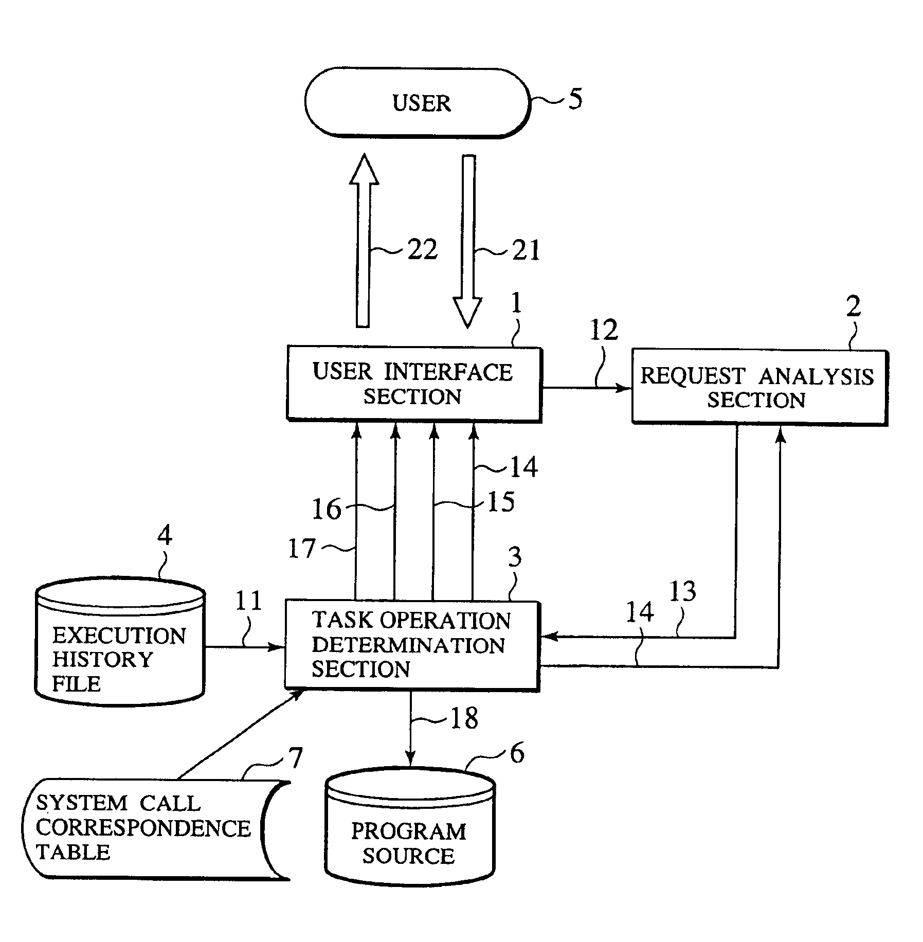
The present invention provides an information processing apparatus that can identify and fix defects in a program by analyzing user behavior and program execution history. The apparatus can display the defect and its solution to the user in real-time, allowing for efficient application development. Additionally, the invention includes a development assistance system that can define the execution environment and check the virtual execution state of a program, identifying program errors and reducing the return of work steps. Overall, the invention improves program quality and efficiency in application development.

Problems solved by technology

Normally, it is not easy to trace the movements of programs so as to analyze the discrepancies of a multitask type application program running on such a real-time OS.
Since the real-time OS adopts a multitask scheme for executing a plurality of programs by changing over tasks operating at specific timing one after another, the defect of the program cannot be analyzed only by tracing one program.
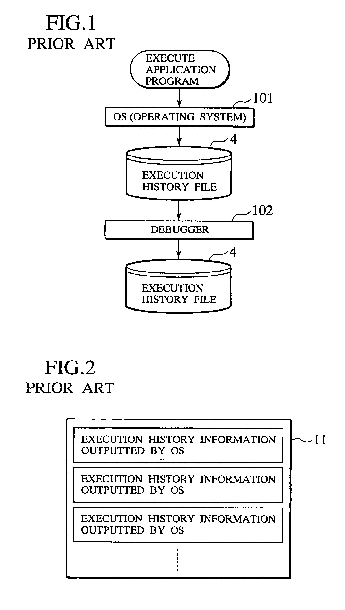
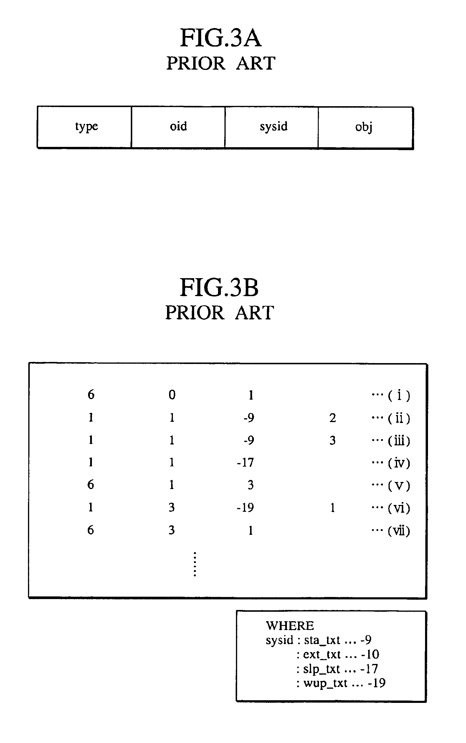
As stated above, although program execution history has been able to be stored as data and the history is used as a key to analyze the defect of the program, the following problems arise.
First, because of the memory capacity of a controller, there is a limit to the quantity of history information which can be acquired.
In case of a system intended to be provided at low cost, particularly, the memory capacity of the system is greatly limited.
Due to this, it is quite difficult to analyze a program defect by following a program operation trace using the history information.
As a result, it still takes lot of time to analyze the program defect, which has had great effect on development cost and development time.
Even if one can perform programming in consideration of an interrupt function or the like that execution environment hardware has, there is no way to check the coincidence.

Method used


Image

  • Information processing apparatus, defect analysis program, and defect analysis method
  • Information processing apparatus, defect analysis program, and defect analysis method
  • Information processing apparatus, defect analysis program, and defect analysis method

Examples


first embodiment

[0082](First Embodiment)

[0083]In this embodiment, it is assumed that a program is a alarm function-added clock program. The following three tasks are used in this program:[0084](1) startup (task_ID=1, priority=1) [alarm setting mode];[0085](2) task A (task_ID=2, priority=3) [normal mode]; and[0086](3) task B (task_ID=3, priority=2).

[0087]If an alarm is set (the alarm setting mode is executed), the mode of this program is turned into the normal mode and then the processing is finished. Originally, this program is an application program which was generated while assuming such an operation as that shown in a time chart of FIG. 11. For example, if attention is paid to a point when the processing is finished, the processing is finished at the task A (normal mode), i.e., a finally executed task at that point is the task A, which is the original specification of this program.

[0088]It is assumed that if the program is actually operated, a result shown in FIG. 12 is obtained. When attention ...

second embodiment

[0122](Second Embodiment)

[0123]The following four tasks are employed by a program assumed in this embodiment:[0124](1) startup (task_ID=1, priority=1);[0125](2) task A (task_ID=2, priority=2);[0126](3) task B (task ID=3, priority=2); and[0127](4) task C (task_ID=4, priority=2).[0128](semaphore used: Semaphore (ID=1, initial semaphore counter=0).

[0129]This program is an application program which was originally generated while assuming such an operation as that shown in the time chart of FIG. 22. Therefore, if attention is paid to a point at which the processing is finished, the processing is finished at the task B, i.e., a finally executed task at the point at which the processing is finished is the task B, which is the original specification of this program.

[0130]It is assumed that if this program is actually operated, a result shown in FIG. 23 is obtained. The execution result shows “Idle Mode” (a state in which no task exists in a ready queue).

[0131]Under these situations, a user ...

third embodiment

[0183](Third Embodiment)

[0184]An application program development assistance system according to the present invention will be described by way of a third embodiment. In this present embodiment, a description will be given to an example of developing an application program that corresponds to a real time OS (μITRON 3.0 specification) incorporated into a microcomputer.

[0185][Configuration of Hardware Resource]

[0186]FIG. 30 is a schematic view showing a configuration of a hardware resource for implementing an application development system 20 according to the present embodiment.

[0187]As shown in FIG. 30, the hardware resource 10 comprises a central processing unit (CPU) 51 and a RAM 52. In the present embodiment, the central processing unit (CPU) 51 and RAM 52 are connected to a ROM 53, a communication device 54, an auxiliary storage device 55, a display device 56, an input device 57, and an output device 59 via a bus 58.

[0188]The ROM 53 and the auxiliary storage device 55 record compu...


PUM


Abstract

The present invention has an display section for displaying an operation state of a program to a user in a time series manner based on program execution history information, an input section for allowing the user to designate a portion of a defect in the displayed operation sate, and an operation analysis section for analyzing a cause of the defect from the portion of the defect pointed out from the user by the input section and from the operation state of the program, and for specifying a solution for solving the cause of the defect. The operation analysis section regenerates the operation state on which the specified solution is reflected, and the display section displays the cause of the defect, the solution and the regenerated operation state to the user.

Description

CROSS REFERENCE TO RELATED APPLICATIONS[0001]This patent application claims for benefit of the filing date of Japanese Patent Application No. P11-375859 filed on Dec. 28, 1999, and P2000-396112 filed on Dec. 26, 2000; the entire contents of which are hereby incorporated by reference.BACKGROUND OF THE INVENTION[0002]1. Field of the Invention[0003]The present invention relates to an information processing apparatus, a defect analysis program, a defect analysis method and application program development assistance system used for testing and debugging multitask programs operating on a real-time OS (Real-time Operating System).[0004]2. Description of the Related Art[0005]The application range of real-time OS represented by a TRON (The Real-time Operating System Nucleus) goes on increase following the development of microprocessor technique. The real-time OS is applied not only to the industrial field but also to the business equipment field such as communications equipment and office eq...

Claims


Application Information

Patent Timeline
Patent Type & Authority Patents(United States)
IPC IPC(8): G06F11/36G06F11/28G06F11/32
CPCG06F11/28G06F11/3664G06F11/366
Inventor YAMAUCHI, NOBUYUKIMATSUMOTO, NATSUMISAWAOKA, AKIRA
Owner KK TOSHIBA
Learn More