Hydraulic drive device for cargo handling vehicle

a technology of hydraulic drive and cargo handling, which is applied in the direction of positive displacement liquid engines, pumps, machines/engines, etc., can solve the problems of electric motor power consumption, and achieve the effects of reducing power consumption, reducing the descent speed of the object, and reducing the power consumption

Active Publication Date: 2017-04-25
TOYOTA IND CORP
View PDF8 Cites 5 Cited by
  • Summary
  • Abstract
  • Description
  • Claims
  • Application Information

AI Technical Summary

Benefits of technology

[0007]An object of the present invention is to provide a hydraulic drive device for cargo handling vehicle capable of efficiently performing the cargo-handling regeneration in a high load state and ensuring a necessary descent speed with low power consumption in a low load state, in the single descent operation of the object.
[0009]In the foregoing aspect of the present invention, the solenoid-controlled proportional valve opens with the valve travel depending upon the control input of the up-and-down control means when the descent control of the up-and-down control means is performed, in a single descent operation of the object. At this time, the pressure difference between the pressures upstream and downstream of the solenoid-controlled proportional valve becomes large, for example, in a high load state in which there is a cargo on the object, and, therefore, the pressure compensation valve is switched toward the close position. If the valve means is switched to the close position here, there is no hydraulic oil returning from the up-and-down hydraulic cylinder to the tank and the whole hydraulic oil from the up-and-down hydraulic cylinder flows to the hydraulic pump. This enables efficient implementation of the cargo-handling regeneration. Since the pressure difference between the pressures upstream and downstream of the solenoid-controlled proportional valve becomes small, for example, in a low load state in which there is no cargo on the object, the pressure compensation valve is switched toward the open position. When the valve means is switched to the open position here, most of the hydraulic oil from the up-and-down hydraulic cylinder returns to the tank. This ensures a necessary descent speed of the object. Since there is little hydraulic oil flowing to the hydraulic pump, the electric motor is prevented from being driven with supply of power, which can decrease power consumption.
[0010]In the foregoing aspect of the present invention, when the descent operation of the object and another cargo handling operation are performed simultaneously, the valve means is switched to the open position. At this time, a flow rate of the hydraulic oil flowing to the hydraulic pump varies depending upon the cargo weight or load condition on the object. With a decrease of the flow rate of the hydraulic oil flowing to the hydraulic pump, the valve travel of the pressure compensation valve increases so as to increase the hydraulic oil returning to the tank by the decrease of the flow rate. With an increase of the flow rate of the hydraulic oil flowing to the hydraulic pump, the valve travel of the pressure compensation valve decreases so as to decrease the hydraulic oil returning to the tank by the increase of the flow rate. Through these operations, the flow rate of the hydraulic oil flowing from the bottom chamber of the up-and-down hydraulic cylinder is kept substantially constant. Therefore, the descent speed of the object can be kept substantially constant. Since it is possible to perform another cargo handling operation except for the descent of the object by making use of regenerative energy, the power consumption can be reduced.
[0014]Since in the single descent operation of the object the determination on switching of opening and closing of the valve means is made depending upon the difference between the command rotation rate of the electric motor and the actual rotation rate of the electric motor, there is no need for a pressure sensor or the like for control of the valve means. In simultaneous execution of the descent operation of the object and another cargo handling operation, the valve means is switched to the open position, whereby the hydraulic oil from the up-and-down hydraulic cylinder returns to the tank. Therefore, variation in the descent speed of the object can be suppressed even in the case where the other cargo handling operation is carried out during the descent operation of the object.
[0018]For example, in the case of the cargo handling vehicle equipped with hydraulic power steering, the hydraulic pump needs to be kept rotating at a rotation rate not less than the idle rotation rate for power steering, during a forward or backward moving state. When the single descent operation of the object is performed in the state in which the running direction of the cargo handling vehicle is forward or backward, the power drive torque limit value of the electric motor is set based on the actual rotation rate of the electric motor and the target rotation rate. For example, the power drive torque limit value of the electric motor is set so that the rotation rate of the hydraulic pump becomes not less than the idle rotation rate. By this setting, the hydraulic pump rotates at the rotation rate not less than the idle rotation rate in the state in which the running direction of the cargo handling vehicle is forward or backward, which ensures smooth steering during the single descent operation of the object. When the rotation rate of the hydraulic pump is the idle rotation rate, the hydraulic pump rotates at the necessary minimum rotation rate, which reduces power consumption.

Problems solved by technology

In this case, the electric motor consumes power.

Method used


Image

  • Hydraulic drive device for cargo handling vehicle
  • Hydraulic drive device for cargo handling vehicle
  • Hydraulic drive device for cargo handling vehicle

Examples


first embodiment

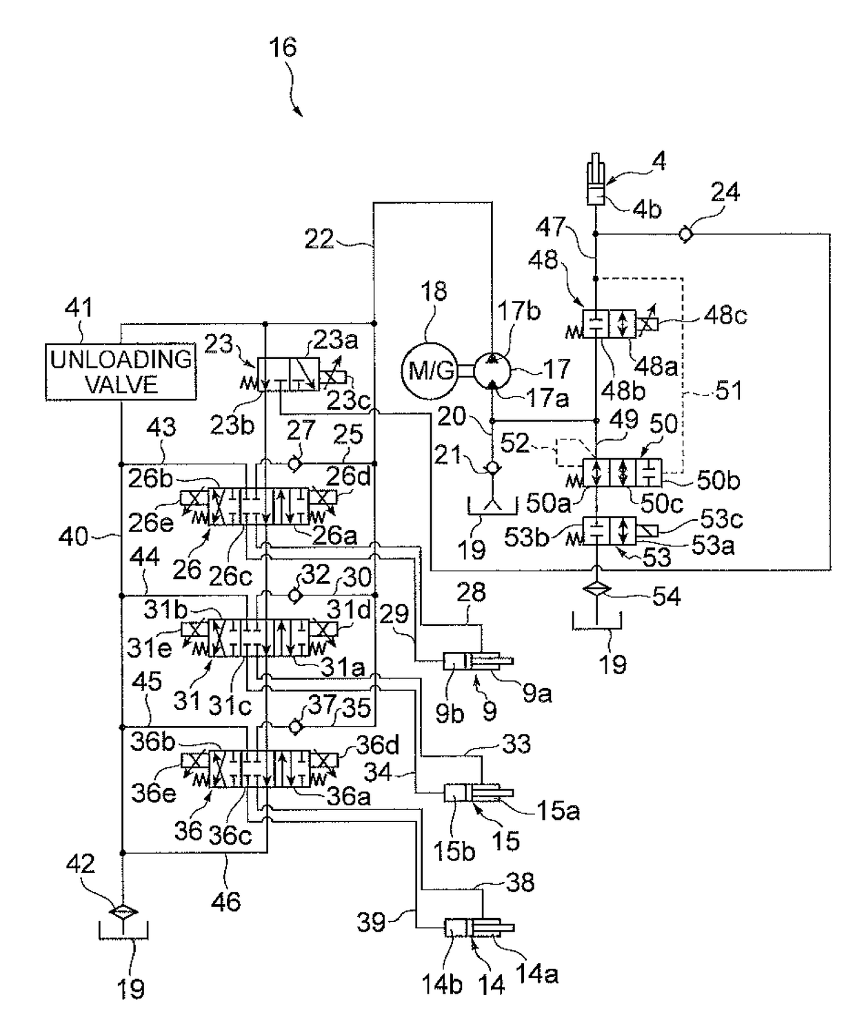
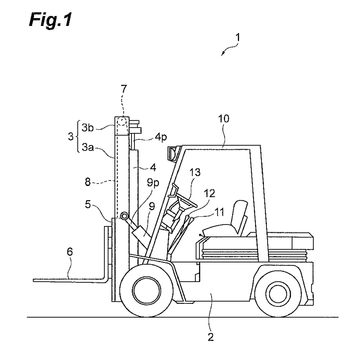
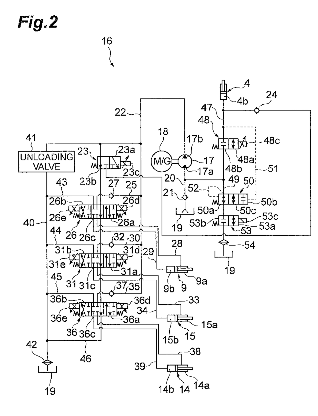
[0048]FIG. 1 is a side view showing a cargo handling vehicle with a hydraulic drive device according to the In the same drawing, the cargo handling vehicle 1 according to the present embodiment is a battery-powered forklift. The forklift 1 is provided with a body frame 2 and a mast 3 arranged in the front part of the body frame 2. The mast 3 consists of a right and left pair of outer masts 3a and inner masts 3b. Each outer mast 3a is supported on the body frame 2 so as to be tiltable. Each inner mast 3b is arranged inside the outer mast 3a and is movable up and down relative to the outer mast 3a.

[0049]A lift cylinder 4 as an up-and-down hydraulic cylinder is arranged on the back of the mast 3. The top end of a piston rod 4p of the lift cylinder 4 is coupled to the upper part of the inner masts 3b.

[0050]A lift bracket 5 is supported on the inner masts 3b so as to be movable up and down. A fork (up-and-down object) 6 to carry a cargo is attached to the lift bracket 5. A chain wheel...

second embodiment

[0122]FIG. 12 is a configuration diagram showing a control system of the hydraulic drive device according to the In the same drawing, the hydraulic drive device 16 of the present embodiment is further equipped with a direction sensor (running direction detecting means) 90, in addition to the configuration shown in FIG. 3.

[0123]The direction sensor 90 detects a running direction (forward, backward, or neutral) of the forklift 1 selected through the direction switch (described above). When the direction switch is switched to forward or backward, the direction sensor 90 turns ON. When the direction switch is switched to neutral, the direction sensor 90 turns OFF.

[0124]The controller 60 receives the detected values from the control lever control input sensors 55-57, the steering control speed sensor 58, and the rotation rate sensor 59 and the detection signal from the direction sensor 90, and performs predetermined processing to control the electric motor 18, the solenoid-controlled pr...


PUM


Abstract

A hydraulic drive device for cargo handling vehicle has: a tank; a pump for drawing in a hydraulic oil from the tank and supplying the hydraulic oil to hydraulic cylinders; an electric motor for driving the pump; a solenoid-controlled proportional valve disposed between an inlet port of the pump and a bottom chamber of an up-and-down hydraulic cylinder and configured to open with a valve travel depending upon a control input of a descent control of an up-and-down control member; a pressure compensation valve disposed between a branch portion located between the pump and the solenoid-controlled proportional valve and the tank and configured to open with a valve travel depending upon a pressure difference between pressures upstream and downstream of the solenoid-controlled proportional valve; and a valve disposed between the pressure compensation valve and the tank and configured to be switched between an open position and a close position.

Description

BACKGROUND OF THE INVENTION[0001]Field of the Invention[0002]The present invention relates to a hydraulic drive device for cargo handling vehicle.[0003]Related Background Art[0004]A battery-powered forklift, which is one of cargo handling vehicles, is provided, for example, with a lift cylinder for moving a fork up and down, a tilt cylinder for tilting a mast, a hydraulic pump for supplying hydraulic oil to the lift cylinder and the tilt cylinder, and an electric motor for driving the hydraulic pump. The battery-powered forklift is sometimes subjected to cargo-handling regeneration as described below. During an operation of lowering a cargo with the fork, the hydraulic oil is returned from the lift cylinder to the hydraulic pump by making use of the weight of the cargo. This causes the hydraulic pump to drive the electric motor, whereby the electric motor comes to generate electric power. When the pressure of the return oil to the hydraulic pump is low, e.g., in a state in which the...

Claims


Application Information

Patent Timeline
Patent Type & Authority Patents(United States)
IPC IPC(8): F04B35/04B66F9/22F15B21/14
CPCF04B35/045B66F9/22F15B21/14B60L2200/42F15B2211/20515F15B2211/20538F15B2211/20569F15B2211/30595F15B2211/40569F15B2211/4159F15B2211/41572F15B2211/50536F15B2211/7142F15B2211/88B60L1/003B60L1/20B60L2240/36
Inventor UEDA, YUKIMATSUO, TSUTOMOUNO, TAKASHIISHIKAWA, HIROHIKOYOKOMACHI, NAOYA
Owner TOYOTA IND CORP
Why Eureka
Try Eureka