Test device for femoral head prosthesis

a test device and prosthesis technology, applied in the direction of material strength testing goods, structural/machine measurement, using tensile/compressive forces, etc., can solve the problems of insufficient high pressure, inability to use apparatus to implement proof testing, and microscopic defects

Inactive Publication Date: 2005-06-07
SAPHIRWERK INDPROD
View PDF7 Cites 7 Cited by
  • Summary
  • Abstract
  • Description
  • Claims
  • Application Information

AI Technical Summary

Benefits of technology

[0017]The use of this sleeve tube enables the socket, made of metal, to be advantageously insulated from the inner bore wall in order to prevent any deposit of metal parti

Problems solved by technology

Despite the great care taken during the manufacture of such heads, they inevitably include microscopic defects.
A second test implemented by the manufacturers of femoral heads consists in taking samples from the manufacturing batches and subjecting them to a destructive test aimed at determining the mean breakage resistance per batch, for example as a function of the shape of the truncated housing, the quality of the ceramic material, the roughness of the surface and the micro-cracks caused by the manufacturing process.
The test apparatus described hereinbefore does not allow sufficiently high pressures to be used to determine the maximum pressure at which the ball breaks, since the sleeve made of plastic material does not resist such pressure, which can exceed 5000 bars.
Unfortunately, this apparatus cannot be used to implement the Proof test.
Indeed, when this test is implemented, metal particles from the friction of the sh

Method used


Image

  • Test device for femoral head prosthesis
  • Test device for femoral head prosthesis
  • Test device for femoral head prosthesis

Examples


Embodiment Construction

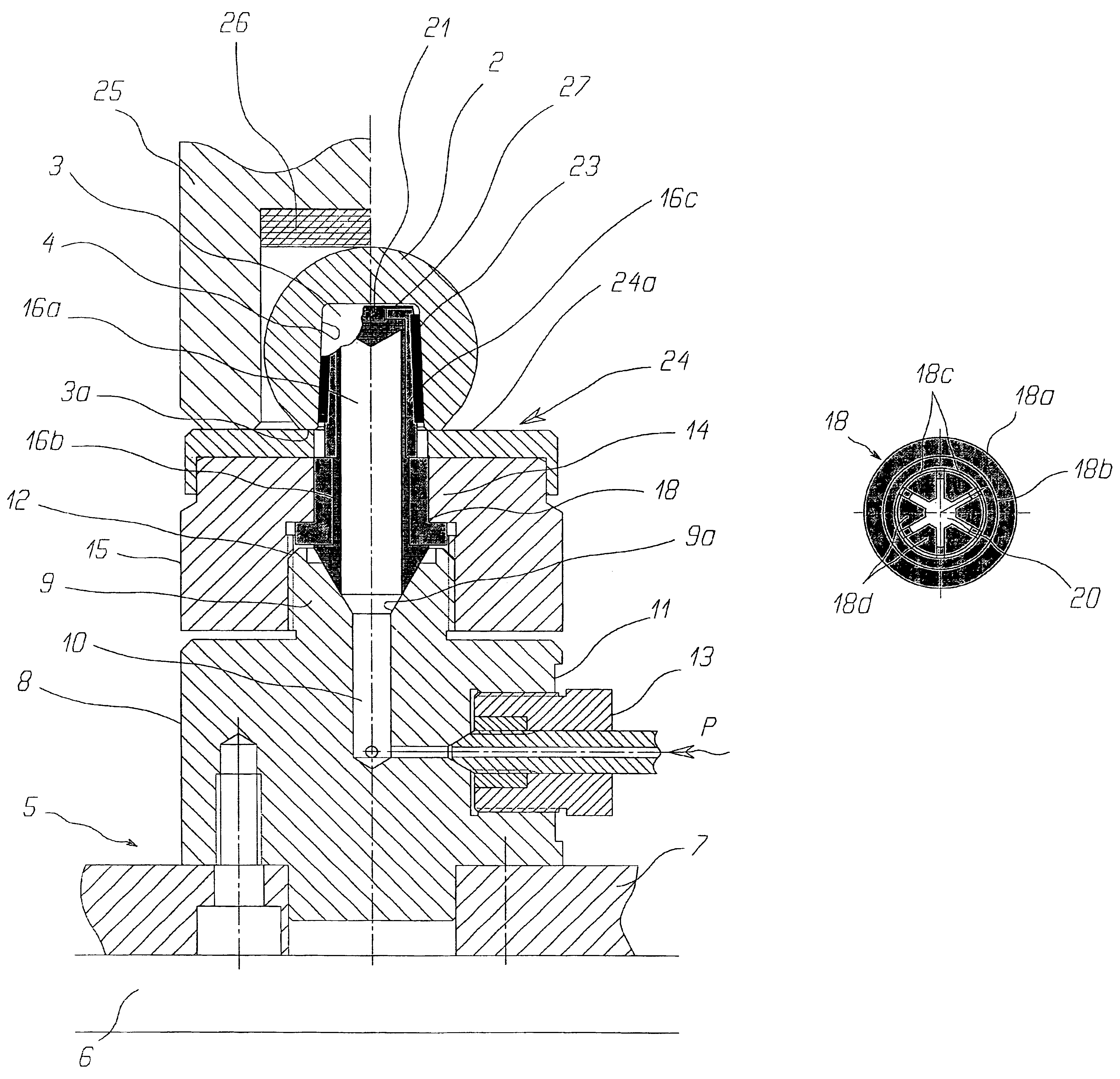
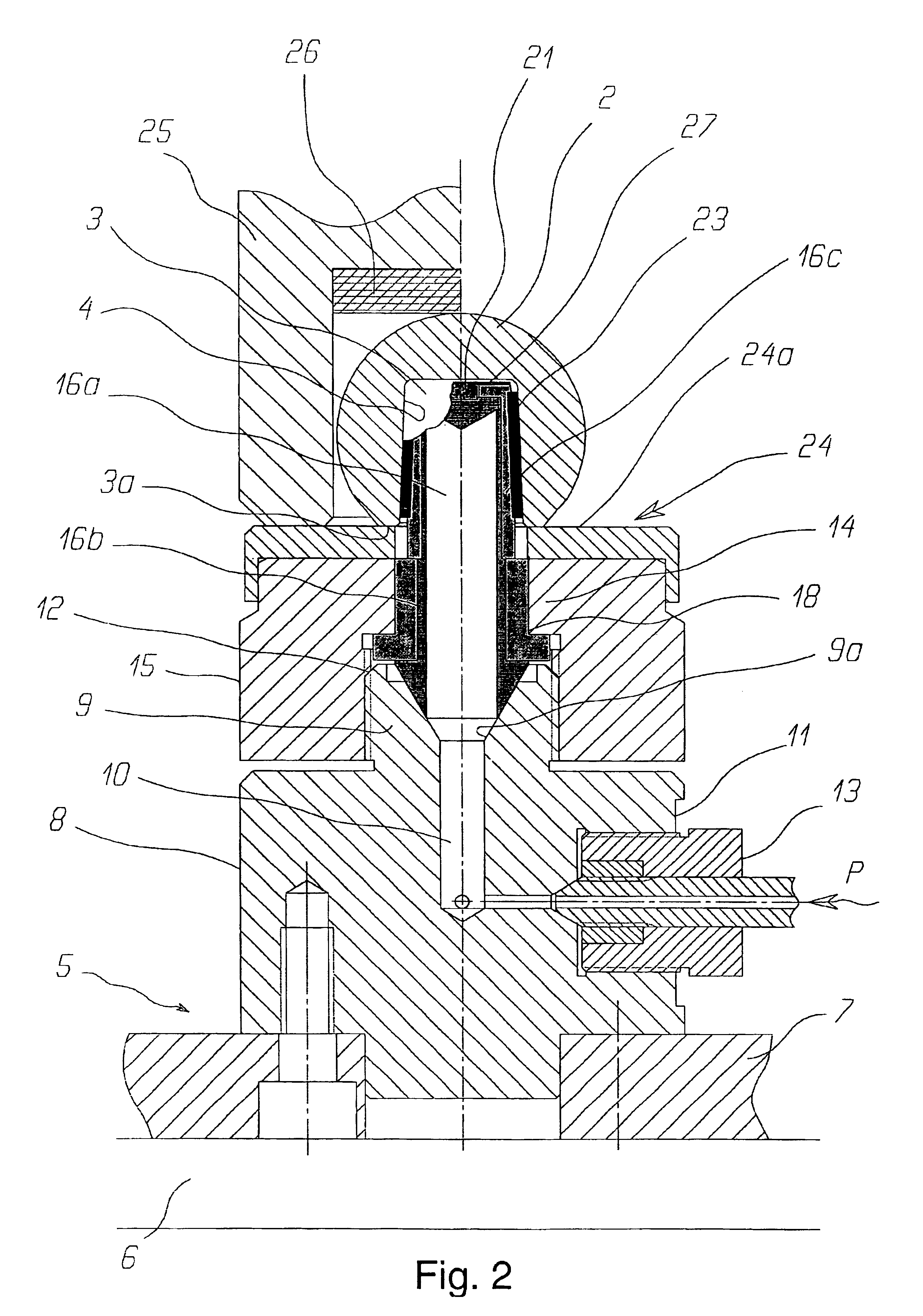
[0024]FIG. 2 shows a device designated by the general reference 1 for testing femoral head prosthesis 2 according to the invention. These heads 2, which are generally made of ceramic material, for example ZrO2, Al2O3, Si3N4, have the general shape of a ball provided with a blind bore 3 for receiving one end of a femoral prosthesis rod (not shown). Bore 3 usually has an inner wall 4 of truncated shape.

[0025]Test device 1 includes a frame 5 including a table 6 bearing a mounting plate 7 which in turn bears a base 8 ending in an end portion 9 provided with an external threading. Base 8 includes a channel 10, which extends from its lateral wall 11 to open out substantially into the end face 12 of end portion 9 via an orifice 9a of truncated shape. The end of channel 10 that opens out onto lateral wall 11 is connected by means of a connector 13 to a fluid pressure source P symbolised by an arrow. A shaft 14 having a substantially complementary shape to bore 3 is fixedly mounted on base 8...


PUM


Abstract

The invention concerns a device for testing, in a destructive or non-destructive manner, femoral head prosthesis having a blind hole for receiving the end of a femoral prosthesis rod. The device includes a frame provided with a shaft projecting from the frame, said shaft having a substantially complementary shape to said bore and being associated with means for applying a pressure onto the inner bore wall when a femoral head is fitted onto said shaft.
This device is characterised in that the shaft includes a sealed jacket having at least one deformable lateral wall portion, and a socket fitted onto said jacket and provided with elastic fingers that extend substantially facing said deformable wall portion of the jacket, and in that said jacket defines an inner chamber in communication with means supplying a pressurized fluid, such that the fluid pressure is transmitted to the inner bore wall via the deformable wall and the elastic fingers.

Description

[0001]This application claims priority from European Patent Application No. 03075495.6, filed Feb. 20, 2003, the entire disclosure of which is incorporated herein by reference.FIELD OF THE INVENTION[0002]The present invention concerns a device for testing femoral head prosthesis, in particular for testing femoral head prosthesis made of ceramic material.BACKGROUND OF THE INVENTION[0003]In a known manner, femoral prosthesis include a femoral rod for implanting in the medullary cavity. The rod ends in a truncated end portion and is covered by fitting a femoral head having the general shape of a sphere. The ball is provided with a blind bore and has a complementary shape to that of the end portion of the femoral rod. These balls, which are most often made of ceramic material, for example ZrO2, Al2O3, Si3N4, etc., are subjected during use to high mechanical stresses and must consequently answer elevated reliability criteria.[0004]Despite the great care taken during the manufacture of su...

Claims


Application Information

Patent Timeline
IPC IPC(8): A61F2/46G01N3/10A61F2/00A61F2/36G01N3/04G01N3/02G01N3/00G01N33/38G01N3/12A61B17/58
CPCA61F2/468G01N3/10G01N2203/0452A61F2002/3611A61F2002/365A61F2220/0033A61F2310/00203A61F2310/00239A61F2310/00317G01N33/388G01N2203/0067G01N2203/0254G01N2203/027G01N2203/0276A61F2002/30332
Inventor BABLER, JEANBURRI, JURGFELBER, HANSBUNTSCHU, URSSALVISBERG, WERNER
Owner SAPHIRWERK INDPROD
Why Eureka
Try Eureka