
Blast attenuation device and method

Inactive Publication Date: 2005-06-07
THE BOEING CO
View PDF17 Cites 49 Cited by
  • Summary
  • Abstract
  • Description
  • Claims
  • Application Information

AI Technical Summary

Benefits of technology

[0013]Further, the present invention provides a method of constructing the system for attenuating a pressure blast and mitigating blast damage to a structure. The method includes determining a maximum initial pressure against which the structure is to be protected, determining an acceptable pressure to which the structure may be subjected, and selecting an attenuation material comprised of particles having a desired radius, mass density, and three-dimensional packing factor. A minimum thickness is determined, for example, according to a mathematical expression, for a particle mist of the attenuation material required to reduce the initial pressure to the acceptable pressure. A delivery system is mounted to the exterior surface of the structure such that the system is capable of providing the particle mist at least as thick as the determined minimum thickness.

Problems solved by technology

Whether intentionally or unintentionally initiated, such blasts can result in severe damage to buildings, vehicles, and personnel.
For example, a blast from a bomb that is detonated in a car parked near a building can cause structural damage to the building, damage components therein, and / or injure people within the building.
Similarly, ballistic and aerial explosive devices can cause costly damage to buildings and other types of structures.
An explosion originating in a cargo container can rupture the container and propagate therefrom.
In some cases, however, the blast may refract over or around the barrier and propagate into the protected area.
Additionally, the construction of barrier devices can be prohibitively expensive, and such barriers can be impractical for protecting high structures, structures in densely populated regions, mobile structures, or underwater structures.
Further, barriers can detract from the aesthetic appeal of a structure or area.

Method used


Image

  • Blast attenuation device and method
  • Blast attenuation device and method
  • Blast attenuation device and method

Examples


Embodiment Construction

[0020]The present inventions now will be described more fully hereinafter with reference to the accompanying drawings, in which some, but not all embodiments of the inventions are shown. Indeed, these inventions may be embodied in many different forms and should not be construed as limited to the embodiments set forth herein; rather, these embodiments are provided so that this disclosure will satisfy applicable legal requirements. Like numbers refer to like elements throughout.

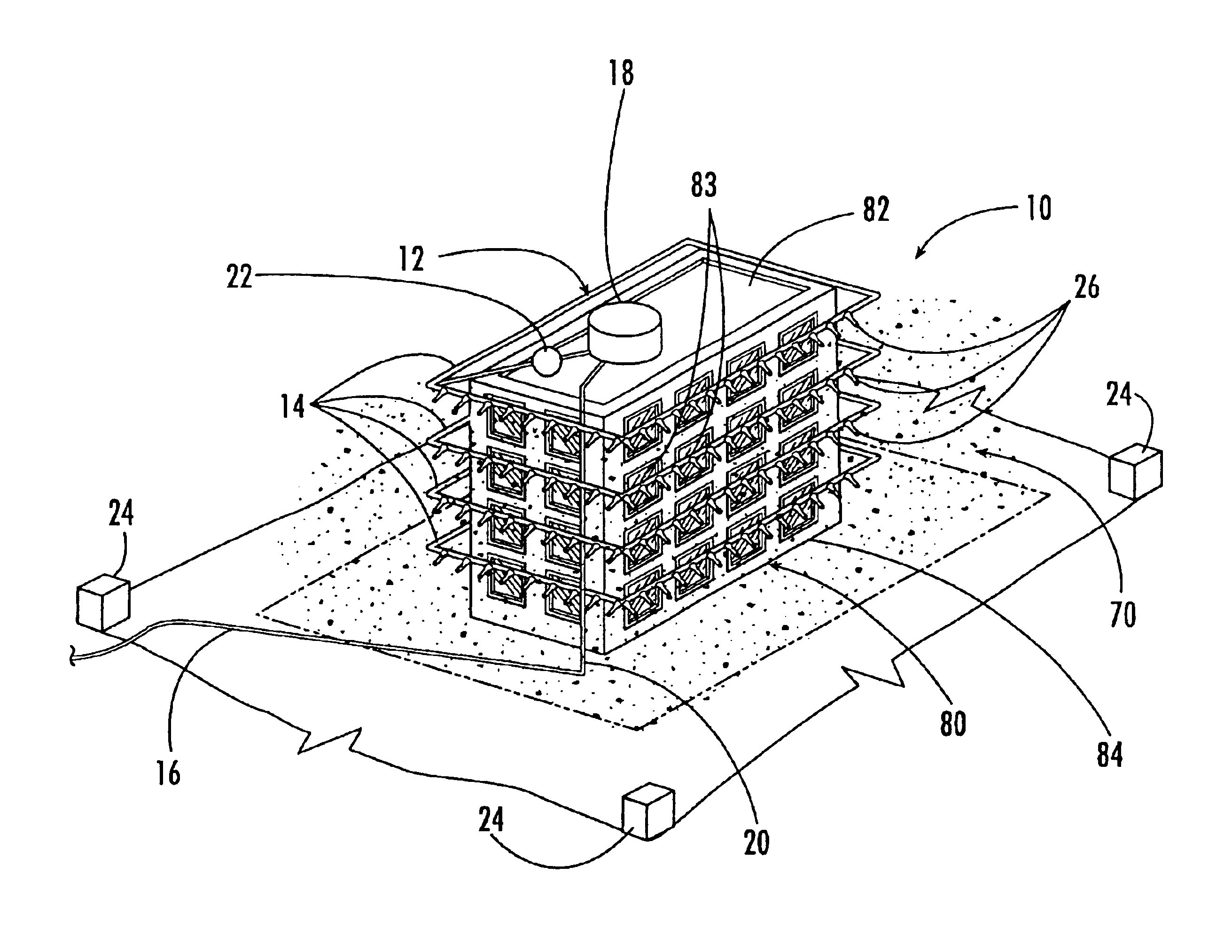
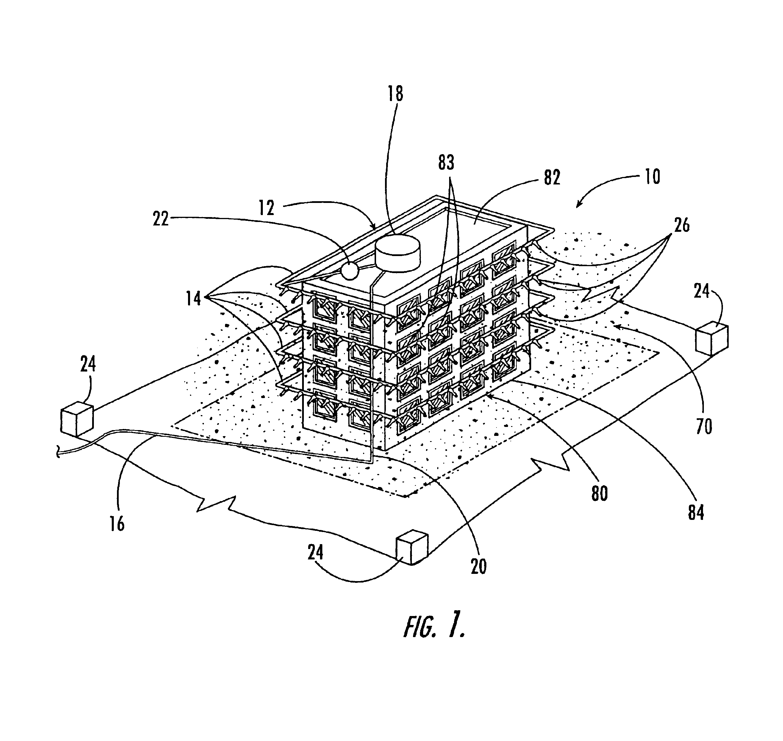
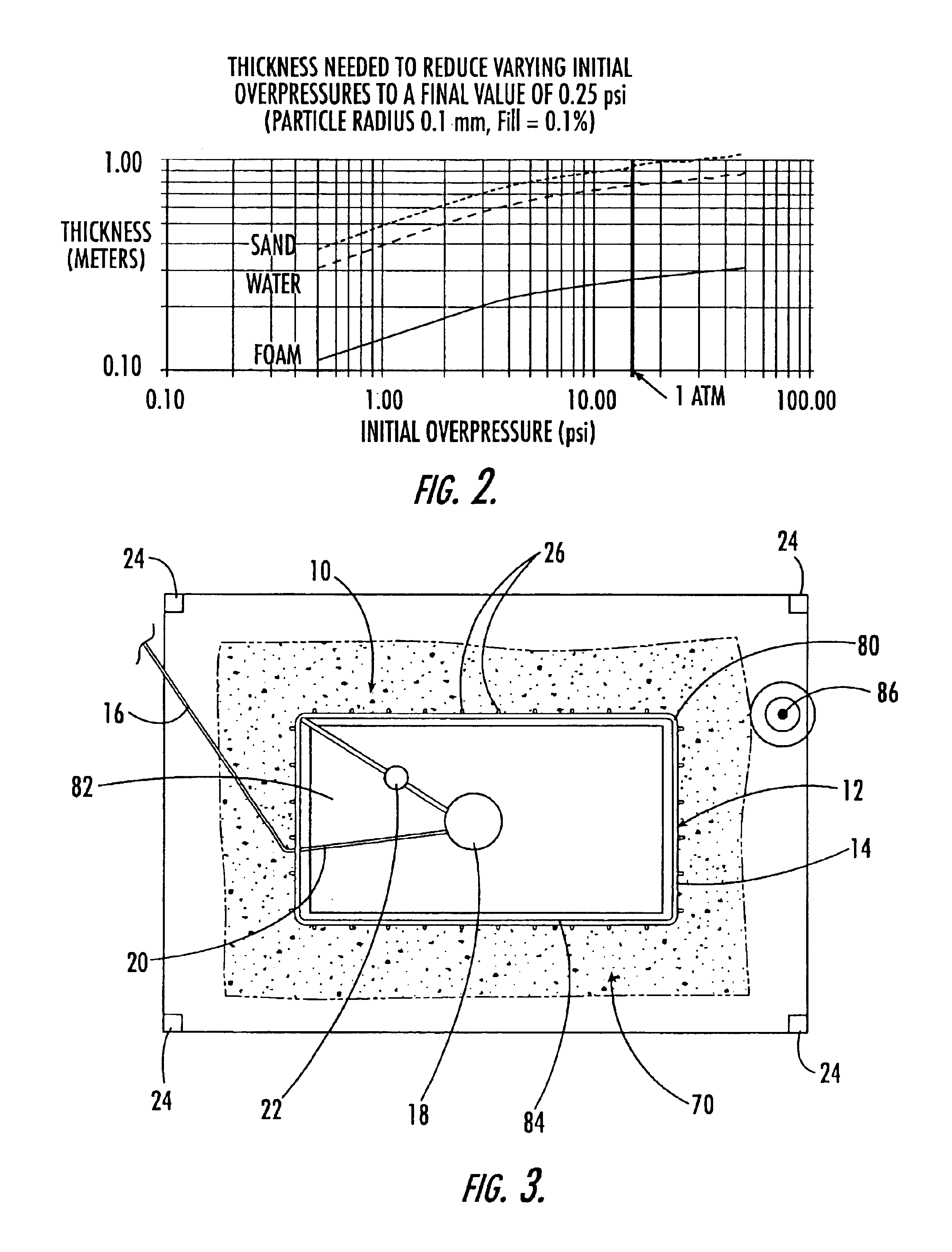
[0021]Referring now to the figures, and in particular FIG. 1, there is shown a blast attenuation system 10 according to one embodiment of the present invention, which is configured to provide an attenuation shield 70 around a protected area 80. The blast attenuation system 10 can similarly be used to protect other areas of any size and shape. Each protected area 80 can also include one or more structures such as buildings 82 or vehicles. The blast attenuation system 10 includes a delivery system 12 that includ...


PUM


Abstract

The present invention provides systems and methods for producing a shield for protecting an area from a pressure blast. The shield, which attenuates the pressure blast, can be used with tall, mobile, and underwater structures, including structures in densely populated areas. One system includes a source for providing an attenuation material, a delivery system that delivers the attenuation material to nozzles, and at least one valve device to control the delivery. A detector is configured to actuate the valve device to an open position in response to a perceived blast threat so that the delivery system delivers the attenuation material to form the shield proximate to a periphery of the protected area.

Description

CROSS-REFERENCE TO RELATED APPLICATION[0001]This application is a divisional of U.S. application Ser. No. 10 / 313,834, filed Dec. 6, 2002 now U.S. Pat. No. 6,805,035, which is hereby incorporated herein in its entirety by reference.BACKGROUND OF THE INVENTION[0002]1) Field of the Invention[0003]The present invention relates to the attenuation of blasts and, in particular, to apparatuses and methods for attenuating blasts with a shield formed of attenuation, or absorptive, material.[0004]2) Description of Related Art[0005]An explosion is typically characterized by a blast or sharp increase in pressure that propagates in a wavelike manner outward from a point or area of origination. Whether intentionally or unintentionally initiated, such blasts can result in severe damage to buildings, vehicles, and personnel. For example, a blast from a bomb that is detonated in a car parked near a building can cause structural damage to the building, damage components therein, and / or injure people w...

Claims


Application Information

Patent Timeline
IPC IPC(8): F42D5/00F42D5/045B65D90/32
CPCF42D5/045B65D90/325
Inventor EDBERG, DONALD L.SCHNEIDER, STANLEY
Owner THE BOEING CO
Learn More