
Variable runner length intake manifold

a technology of intake manifold and runner length, which is applied in the direction of air intake for fuel, combustion-air/fuel-air treatment, machines/engines, etc., can solve the problem of short intake passage at which the inertia effect is maximized and the effect of increasing the length of the intake passag

Inactive Publication Date: 2005-06-07
TOYOTA MOTOR CO LTD
View PDF7 Cites 11 Cited by
  • Summary
  • Abstract
  • Description
  • Claims
  • Application Information

AI Technical Summary

Benefits of technology

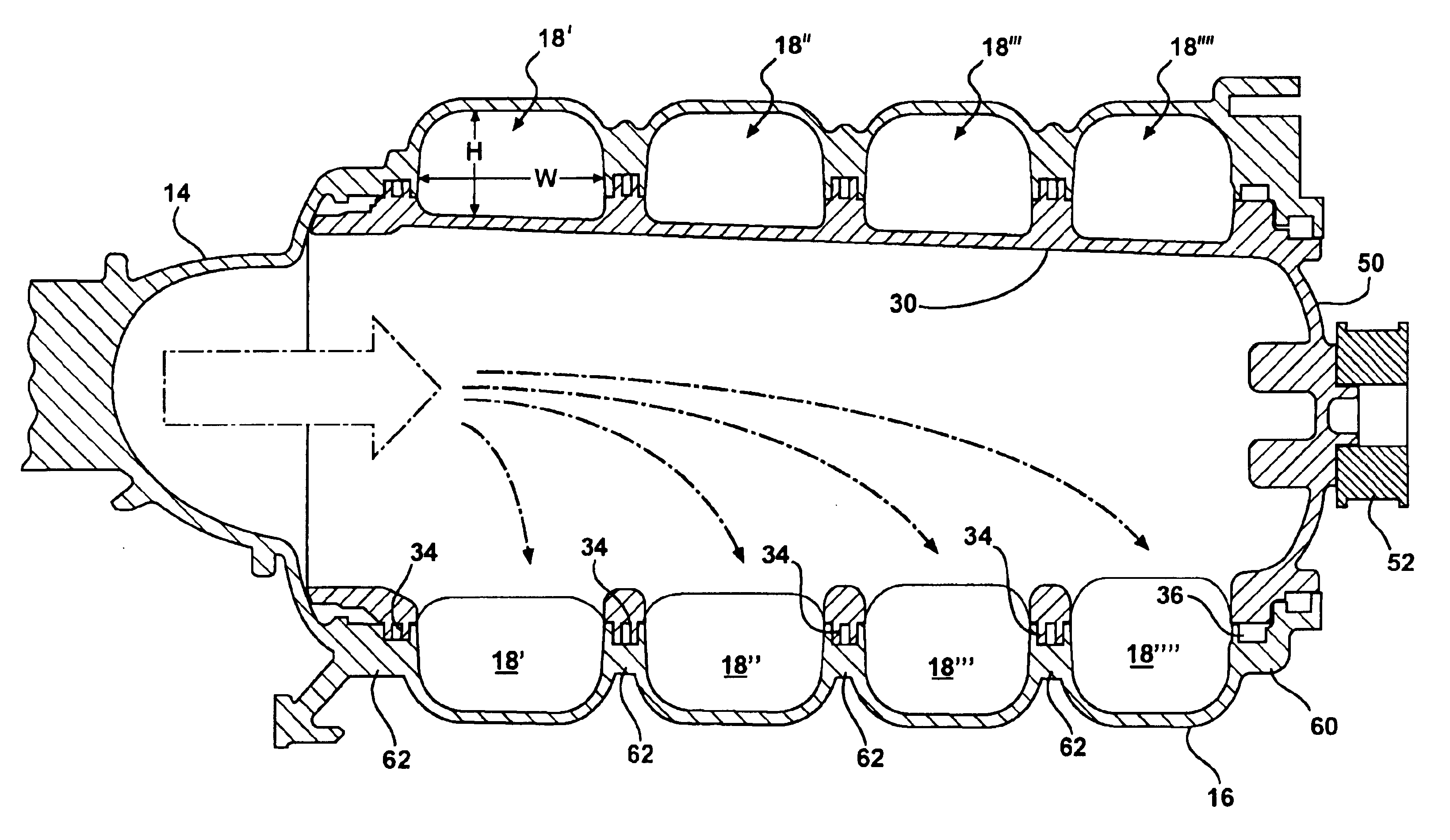
[0004]The present invention provides a variable runner length air intake manifold for an internal combustion engine wherein vehicle performance parameters are optimized over a range of engine speeds, and wherein the flow pattern of the intake air at different runner lengths experiences smooth transition when entering the intake manifold and passing through a rotating interior part such that substantially constant flow resistance is incurred despite the variable runner length.
[0008]The tapered drum is rotatably mounted within the housing and is in communication with a runner length adjuster. The runner length adjuster is operative to rotatably adjust the position of the tapered drum within the housing such that the effective runner length for each of the individual runner lengths is variable. In this manner, a variable runner length air intake manifold for an internal combustion engine is provided that allows for the performance of the internal combustion engine to be optimized over a range of engine speeds.

Problems solved by technology

Particularly, as the engine speed is increased, the length of the intake passage at which the inertia effect is maximized becomes short.
However, many conventional intake manifold systems are still based on a fixed runner length.

Method used


Image

  • Variable runner length intake manifold
  • Variable runner length intake manifold
  • Variable runner length intake manifold

Examples


Embodiment Construction

[0019]The present invention provides a variable runner length air intake manifold that is operative to meet optimum performance levels in power and torque over a range of engine speeds. The invention allows for fast and efficient calibration of performance levels during engine development and evaluation whereby users have flexibility in adjusting the runner length of the air intake manifold such that regulatory requirements are satisfied and performance goals at different engine speeds are readily obtained.

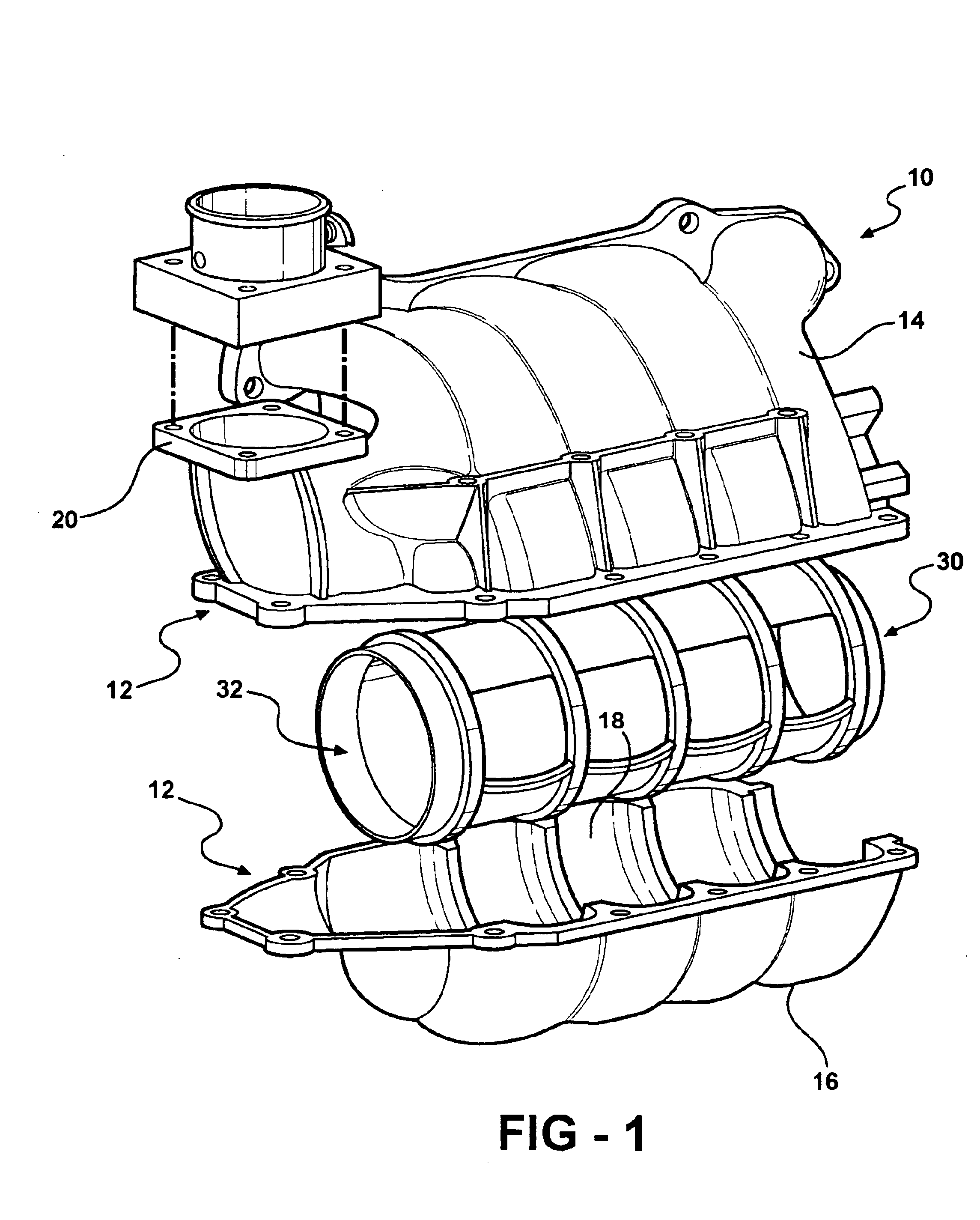
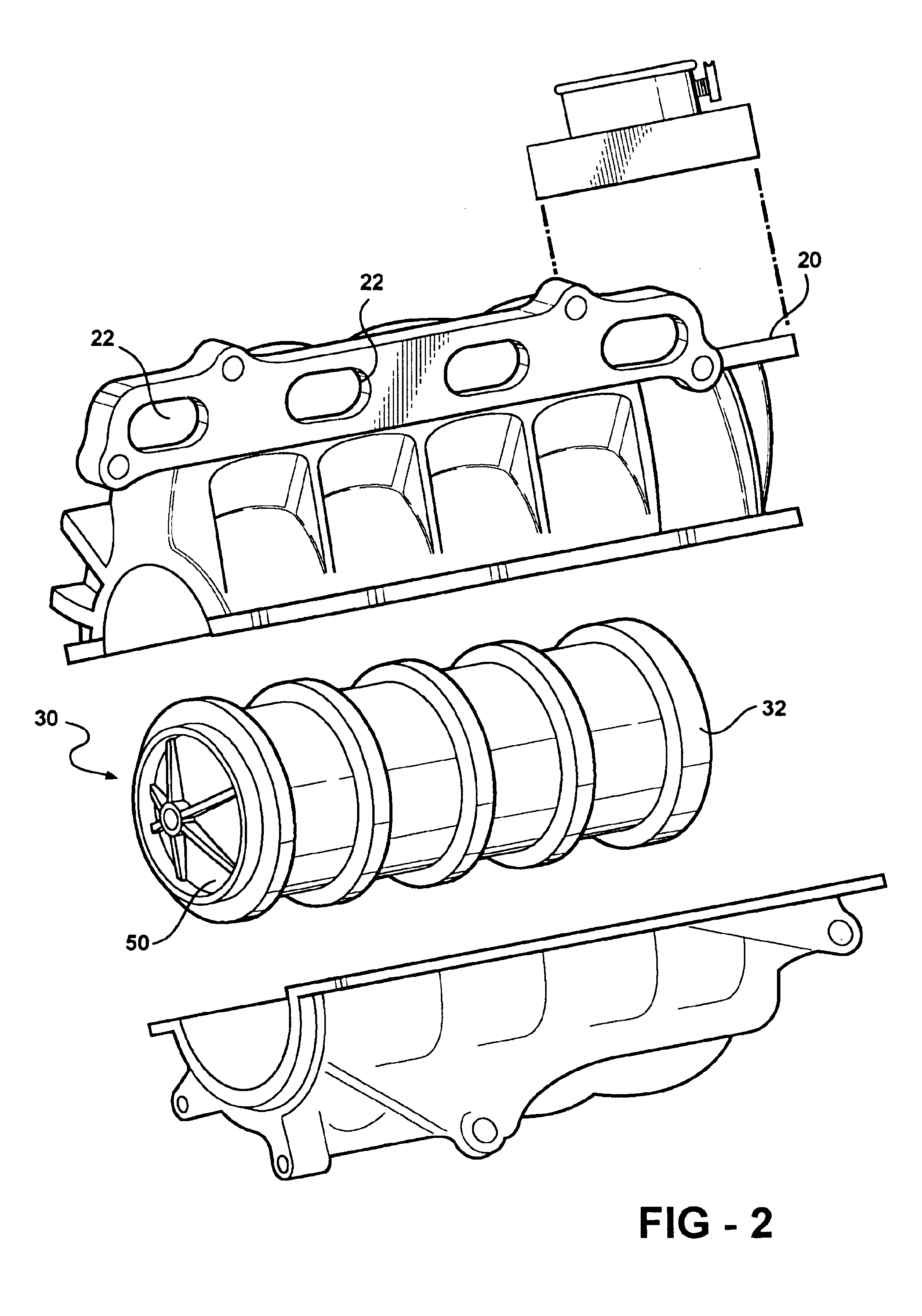
[0020]FIGS. 1 and 2 illustrate exploded perspective views of a variable runner length air intake manifold 10 as according to the invention. The air intake manifold 10 includes a housing 12 formed of upper 14 and lower 16 halves operative to be fixedly attached via a conventional fastening means. The manifold housing 12 cooperates with a tapered drum disposed therein to define a plurality of runners 18′-18″″ having equivalent cross-sectional areas but different cross-sectional shap...


PUM

PropertyMeasurementUnit
lengthaaaaaaaaaa
lengthaaaaaaaaaa
lengthaaaaaaaaaa

Abstract

The present invention provides a variable runner length intake air manifold operative to optimize the performance of an internal combustion engine over a wide range of engine speeds. The manifold includes a housing formed of upper and lower halves fixedly attached via conventional fastening means. The upper and lower halves define a plurality of runners having constant cross-sectional areas but different cross-sectional shapes. A tapered drum is disposed within the housing and includes one open end and a plurality of openings formed in the outer surface that communicate with corresponding runners of the housing. The tapered drum is rotatably mounted within the housing such that the effective runner length or airflow path of the manifold is made adjustable by varying the angular position of the tapered drum disposed within the housing.

Description

FIELD OF THE INVENTION[0001]The present invention relates to a variable runner length intake manifold for an internal combustion engine and more particularly to a runner length that can be adjusted based on engine speed such that the runner length is at all times set to an optimal length.BACKGROUND OF THE INVENTION[0002]The performance of an engine at wide-open throttle is often judged by the breathing characteristics of induction, intake and exhaust systems. Tuning and ramping effects at mid and high engine speeds assist air motion through the engine's air intake manifold and into engine cylinders. By utilizing the so-called inertia effect of intake gas, the volumetric efficiency of an internal combustion engine can be improved whereby the output power of the engine can be enhanced. The intake inertia effect depends upon the length of the intake passage of the engine and the engine speed. Particularly, as the engine speed is increased, the length of the intake passage at which the ...

Claims


Application Information

Patent Timeline
Patent Type & Authority Patents(United States)
IPC IPC(8): F02M35/10F02B27/02
CPCF02B27/0257F02B27/0263F02B27/0284F02M35/10039Y02T10/146F02M35/10321F02M35/10327F02M35/10347F02B27/0215Y02T10/12
Inventor OBERG, ERIK JOHNSHIEH, TENG-HUA
Owner TOYOTA MOTOR CO LTD
Learn More