Variable stiffness fuel rail pulse damper having extended dynamic range

a technology of dynamic range and fuel rail, which is applied in the direction of liquid fuel feeders, machines/engines, fuel injecting pumps, etc., can solve the problems of increasing the hardware cost of an engine, reducing the efficiency of the engine, and pulsating pressure in the fuel itself, so as to reduce the resultant stress and reduce the effect of mechanical cos

Inactive Publication Date: 2005-06-07
DELPHI TECH INC
View PDF11 Cites 26 Cited by
  • Summary
  • Abstract
  • Description
  • Claims
  • Application Information

AI Technical Summary

Benefits of technology

[0016]A damper in accordance with the invention may assume any of several cross-sectional shapes permitting opposed sides to self-contact, thus increasing the stiffness and minimizing the resultant stresses during high pressure events.
[0017]In a preferred embodiment, the inner surfaces of the opposed long sides are each provided with two opposing longitudinal internal contact points which, when they meet, divide the internal space into a central chamber within the contact points and two peripheral chambers outboard of the contact points within the short sides. Further pressure causes further compression of the central chamber. An important element in providing the extended compression range in some embodiments is that the inner surface within the contact points is shifted into tension after the points make contact, thereby stiffening the damper and increasing the damper's resistance to further deformation.

Problems solved by technology

A well-known problem in fuel rail systems, and especially in returnless systems, is pressure pulsations in the fuel itself.
These provide only point damping and can lose function at low temperatures.
They add hardware cost to an engine, complicate the layout of the fuel rail or fuel line, can allow permeation of fuel vapor, and in many cases simply do not provide adequate damping.
This configuration can provide excellent damping over a limited range of pressure fluctuations but it is not readily enlarged to meet more stringent requirements for pulse suppression.
Reducing wall thickness is not desirable because it reduces the functional margin between stress and yield.
Increasing the size of a fuel rail to accommodate a damper having a larger diameter or longer length is highly undesirable because the space adjacent the engine in a vehicle is already highly congested and limited, and because a new fuel rail design or layout increases the cost of manufacturing an engine.

Method used


Image

  • Variable stiffness fuel rail pulse damper having extended dynamic range
  • Variable stiffness fuel rail pulse damper having extended dynamic range
  • Variable stiffness fuel rail pulse damper having extended dynamic range

Examples


embodiment 500

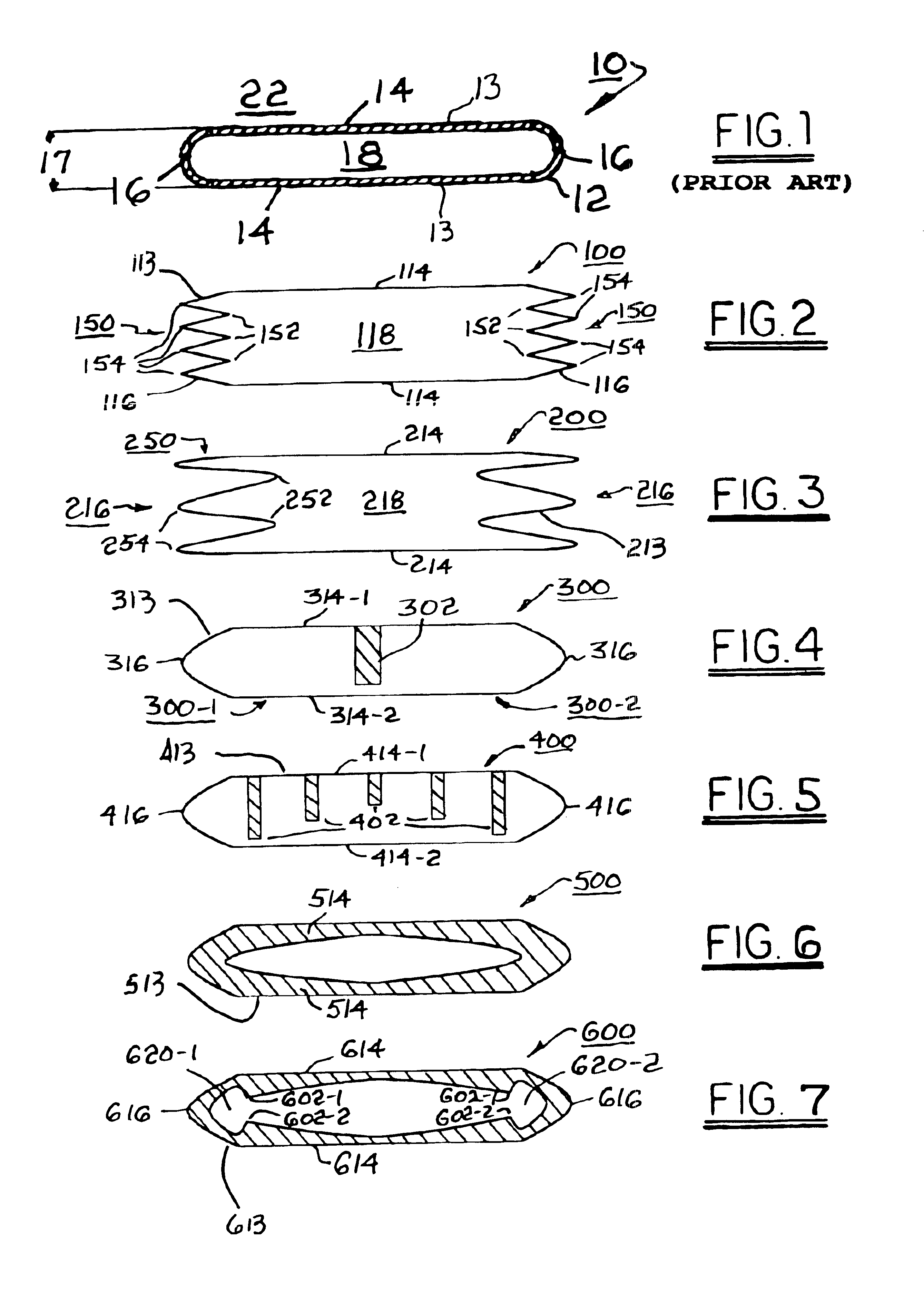
[0032]Referring to FIG. 6, in embodiment 500, walls 513 having diaphragm sides 514 have significant thickness, and taper in thickness from center to edge. Sides 514 can flex inwards under pressure. Under a predetermined external pressure, sides 514 self-contact. Due to the cross-sectional shape, the self-contact will initiate closer to the sides of the damper and work its way progressively towards the center of the damper as pressure continues to increase. This embodiment provides a continuously variable damper response characteristic.

[0033]Referring to FIG. 7, embodiment 600 is similar to embodiment 500 in having walls 613 including tapered diaphragm sides 614, but short sides 616 are thinned down to provide greater flexure by providing first and second side galleries 620-1, 620-2 further defining first and second contact elements 602-1, 602-2. As pressure is applied to embodiment 600, not only do sides 614 flex inwards, but sides 616 also flex outwards until the contact elements m...
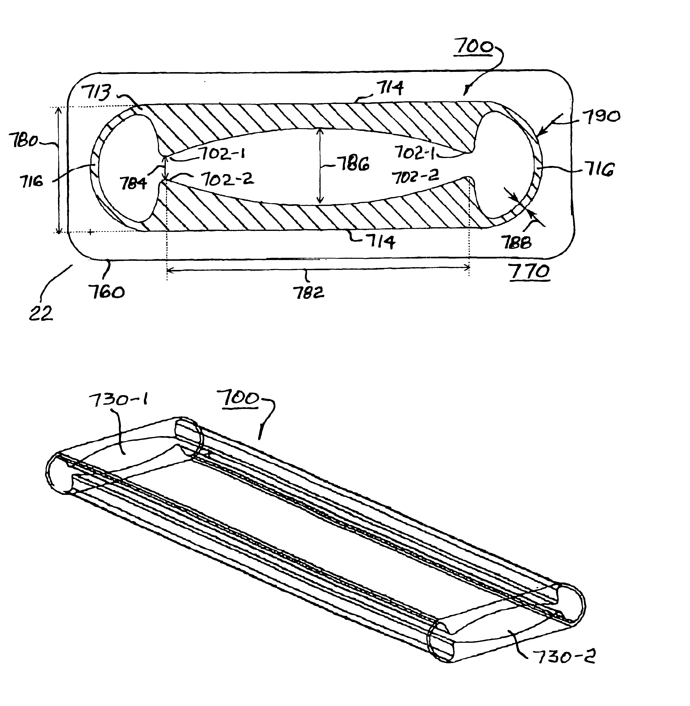
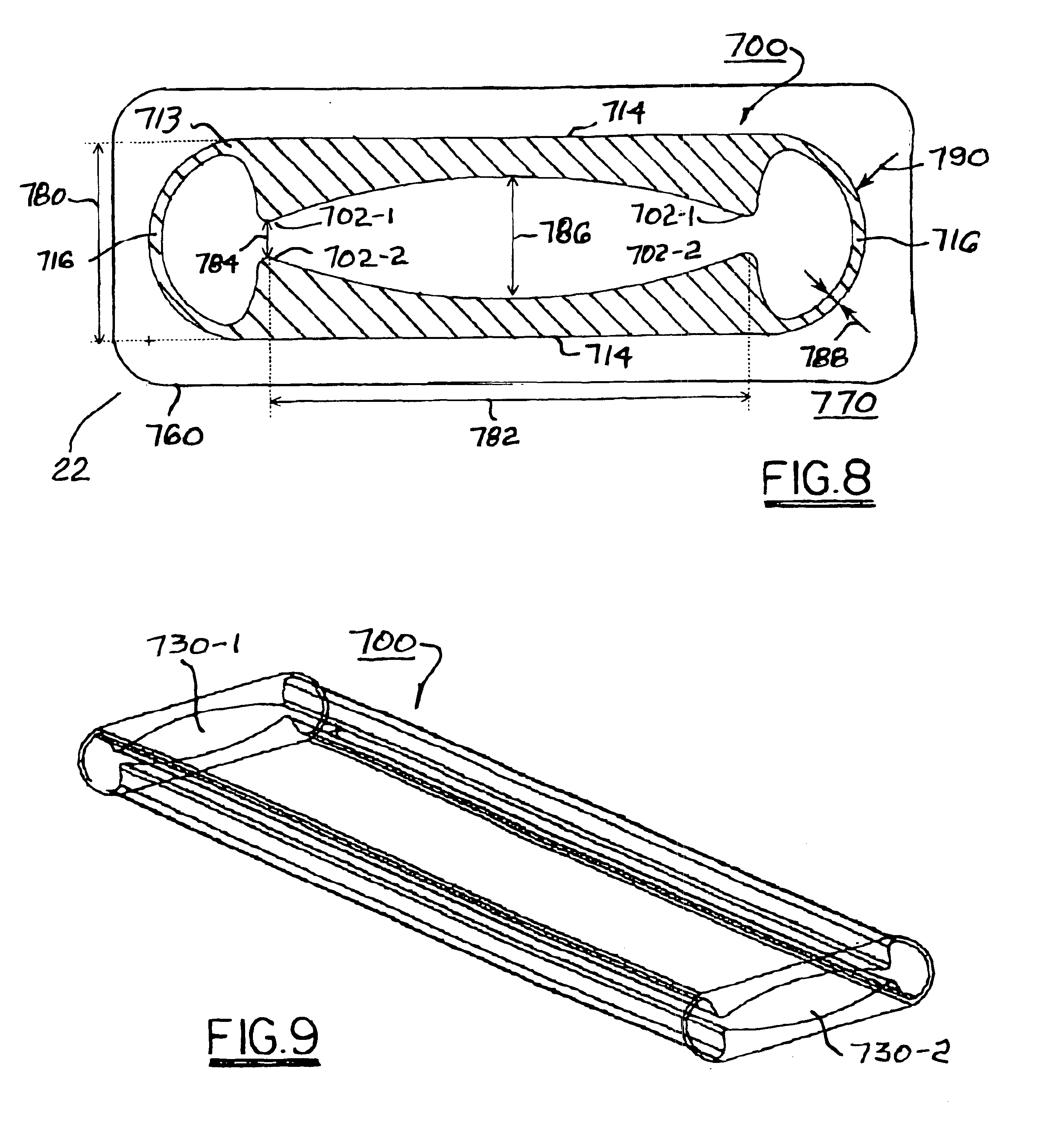
embodiment 700

[0035]Embodiment 700 shown in FIG. 9 is shown as open-ended, but of course that is simply a representative longitudinal portion of an actual damper, which would have ends 730-1,730-21 closed as by separate end pieces (not shown) or by being crimped and fused shut to capture gas within the damper in known fashion.

[0036]Referring to FIGS. 10 through 16, a finite element analysis of embodiment 700 shows deformations of sides 714 and 716 at various external pressures between 0 MPa (FIG. 10) and 1 MPa (FIG. 16). It is seen that contact elements 702-1, 702-2 touch at about 170 kPa (FIG. 12). At pressures below that level, diaphragm sides 714 are urged toward one another almost without deformation by decreasing the radius of curvature of sides 716. Once the contact elements meet, forming lateral chambers 720-1 and 720-2, sides 716 participate very little in further pressure absorption. Embodiment 700 is shifted to a second pressure / response regime wherein deformations of sides 714 are acco...


PUM


Abstract

A fluid pulse damper having increased dynamic range and sensitivity, being especially useful in suppressing pulsations in the fuel supply rail of an internal combustion engine. The damper is a longitudinal gas-filled plastic pillow having walls formed by opposed flexible short sides and opposed flexible long sides, and includes at least one internal self-contact element, and preferably a plurality of such elements. As the short sides flex, the elements make contact internally, shifting the damper into a different compression regime and extending the pressure/response over an increased range of pressures. A feature of some embodiments is that the inner surface within the contact elements is shifted into tension after the elements make contact, thereby stiffening the damper and increasing the damper's resistance to further deformation. The damper is formed of a plastic such as ultra-high molecular weight polyethylenes, high flow polyetherimides, or tubing grade polyphthalamides.

Description

TECHNICAL FIELD[0001]The present invention relates to fuel rails for internal combustion engines; more particularly, to devices for damping pulses in fuel being supplied to an engine via a fuel rail; and most particularly, to an improved fuel rail internal damper having increased dynamic range.BACKGROUND OF THE INVENTION[0002]Fuel rails for supplying fuel to fuel injectors of internal combustion engines are well known. A fuel rail is essentially an elongate fuel manifold connected at an inlet end to a fuel supply system and having a plurality of ports for mating with a plurality of fuel injectors to be supplied.[0003]Fuel rail systems may be recirculating, as is commonly employed in diesel engines. Fuel rails are more typically “returnless” or dead ended, wherein all fuel supplied to the fuel rail is dispensed by the fuel injectors.[0004]A well-known problem in fuel rail systems, and especially in returnless systems, is pressure pulsations in the fuel itself. It is known that fuel s...

Claims


Application Information

Patent Timeline
Patent Type & Authority Patents(United States)
IPC IPC(8): F02M69/46F02M63/00
CPCF02M69/465F02M2200/9015F02M2200/315
Inventor BECENE, AHMET T.BRAUN, CHARLES W.DEANGELIS, GARY J.LEWIS, CHRISTOPHER L.ARVIND, RAO M.
Owner DELPHI TECH INC
Why Eureka
Try Eureka