Display apparatus and backlight apparatus

Inactive Publication Date: 2005-06-07
SHARP KK
View PDF3 Cites 95 Cited by
  • Summary
  • Abstract
  • Description
  • Claims
  • Application Information

AI Technical Summary

Benefits of technology

[0009]A general object of the present invention is to provide an improved and useful backlight apparatus and display apparatus that can prevent a leak of the current from electric wires providin

Problems solved by technology

However, when the coating is thin, it is conceivable that the current slightly leaks from the coated wires to the metal case.
When the current leaks in this manner, the vo

Method used


Image

  • Display apparatus and backlight apparatus
  • Display apparatus and backlight apparatus
  • Display apparatus and backlight apparatus

Examples


Embodiment Construction

[0019]A description will be given of embodiments of the present invention with drawings.

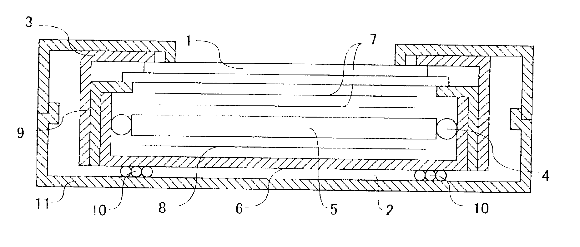
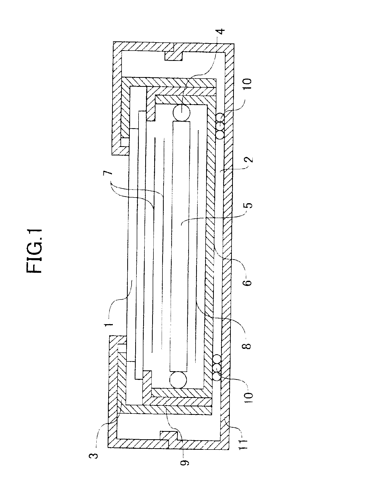
[0020]FIG. 1 is a cross-sectional view of an outline structure of a display apparatus according to the present invention. In FIG. 1, a display element 1 made of a liquid crystal display element, for example, and a backlight apparatus 2 are mounted to a display apparatus cover 3. Then, the display apparatus cover 3 is accommodated in a housing 11 made of resin, for example, and the display apparatus is completed.

[0021]The backlight apparatus 2 includes fluorescent tube lamps 4 that are light-emitting sources, a light guide plate 5 that spreads and diffuses light from the fluorescent tube lamps 4 and radiates the light from a surface, and a backlight frame 6 as a case that accommodates the fluorescent tube lamps 4 and light guide plate 5. Further, in the backlight frame 6, optical sheets 7 are placed on a front side of the light guide plate 5 so as to adjust the light radiated from the light guide ...


PUM


Abstract

A display apparatus comprises a display element, a backlight apparatus provided behind the display element and having a metal case, and a housing accommodating the display element and the backlight apparatus. In the display apparatus, electric wires for providing power to the backlight apparatus extend between the metal case of the backlight apparatus and the housing, and at least one opening is provided in the metal case in a part where the electric wires extend.

Description

BACKGROUND OF THE INVENTION[0001]1. Field of the Invention[0002]The present invention relates to a display apparatus, and more particularly, to a display apparatus that needs a backlight apparatus such as a liquid crystal display.[0003]2. Description of the Related Art[0004]Generally, in a conventional liquid crystal display, a backlight apparatus is positioned behind a liquid crystal display element. Display contents on the liquid crystal display element can be seen by light from the backlight apparatus. In such a liquid crystal display apparatus, the backlight apparatus is incorporated in a housing that accommodates the liquid crystal display element.[0005]The backlight apparatus includes a light-emitting source such as a linear fluorescent tube, for example. A tabular light guide plate is provided adjacent to the light-emitting source. Light from the light-emitting source is incident on the tabular light guide plate, spreads and diffuses within the light guide plate, and is emitt...

Claims


Application Information

Patent Timeline
IPC IPC(8): G06F1/16F21V8/00G02F1/13357F21Y103/00G09F9/00G09F9/35
CPCG06F1/1601G06F2200/1612G02F1/1333
Inventor EIRAKU, TAKAYUKIHAYASHIMOTO, SEIJI
Owner SHARP KK
Why Eureka
Try Eureka