Cutting tool

Inactive Publication Date: 2005-06-07
HILTI AG
View PDF17 Cites 15 Cited by
  • Summary
  • Abstract
  • Description
  • Claims
  • Application Information

AI Technical Summary

Benefits of technology

[0017]In order to insure that the cutting tool, when formed as a core bit, is able to form large diameter bores, the support region is made tubular, with the end surface being formed by the end region of the support region remote from the receiving region. The removal of the cut material is noticeably increases or improved when the receiving region is provided on its inner and/or outer side with at least one helice, respectively.
[

Problems solved by technology

Such cutting elements are unsuitab

Method used


Image

  • Cutting tool
  • Cutting tool
  • Cutting tool

Examples


Example

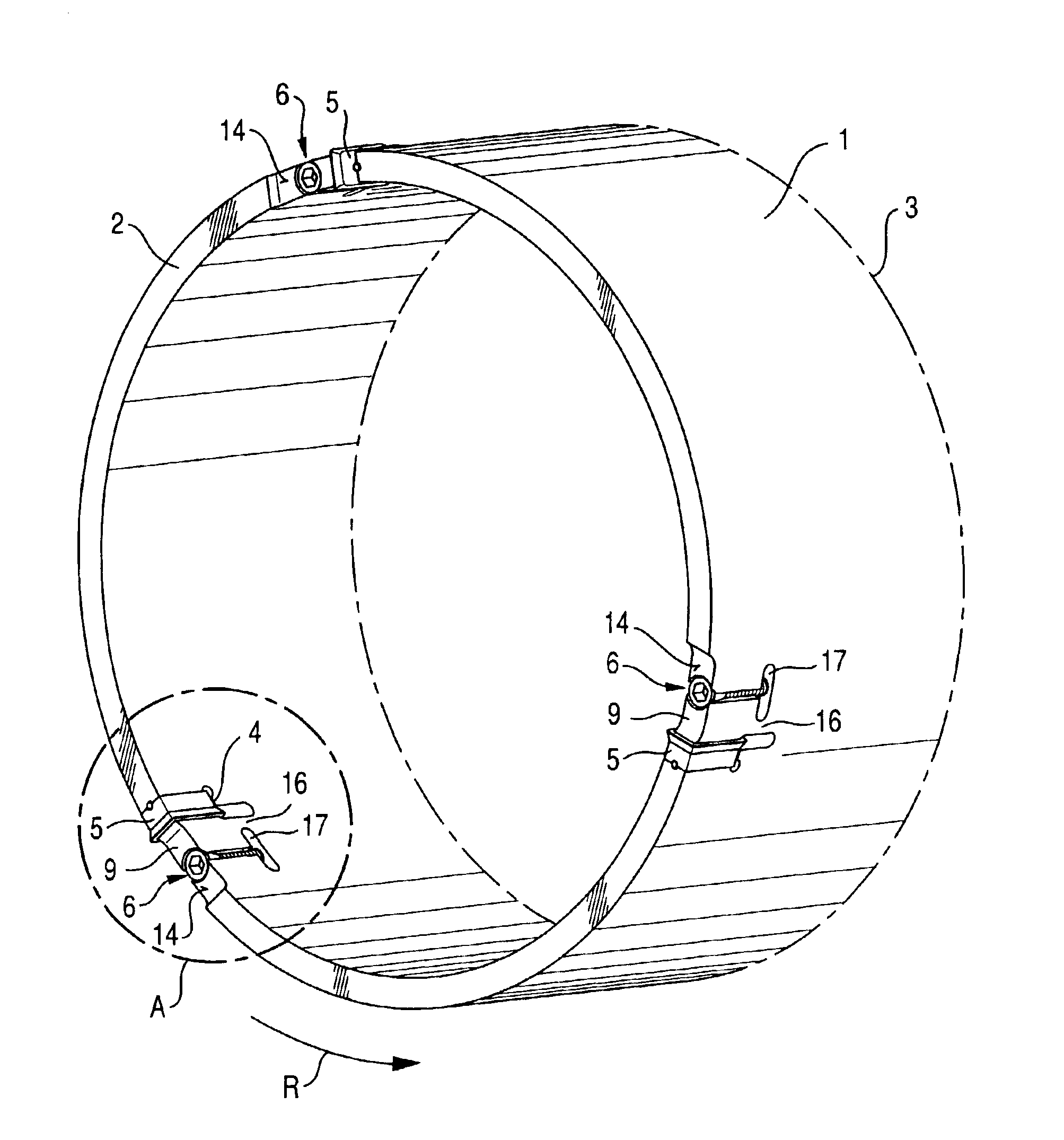
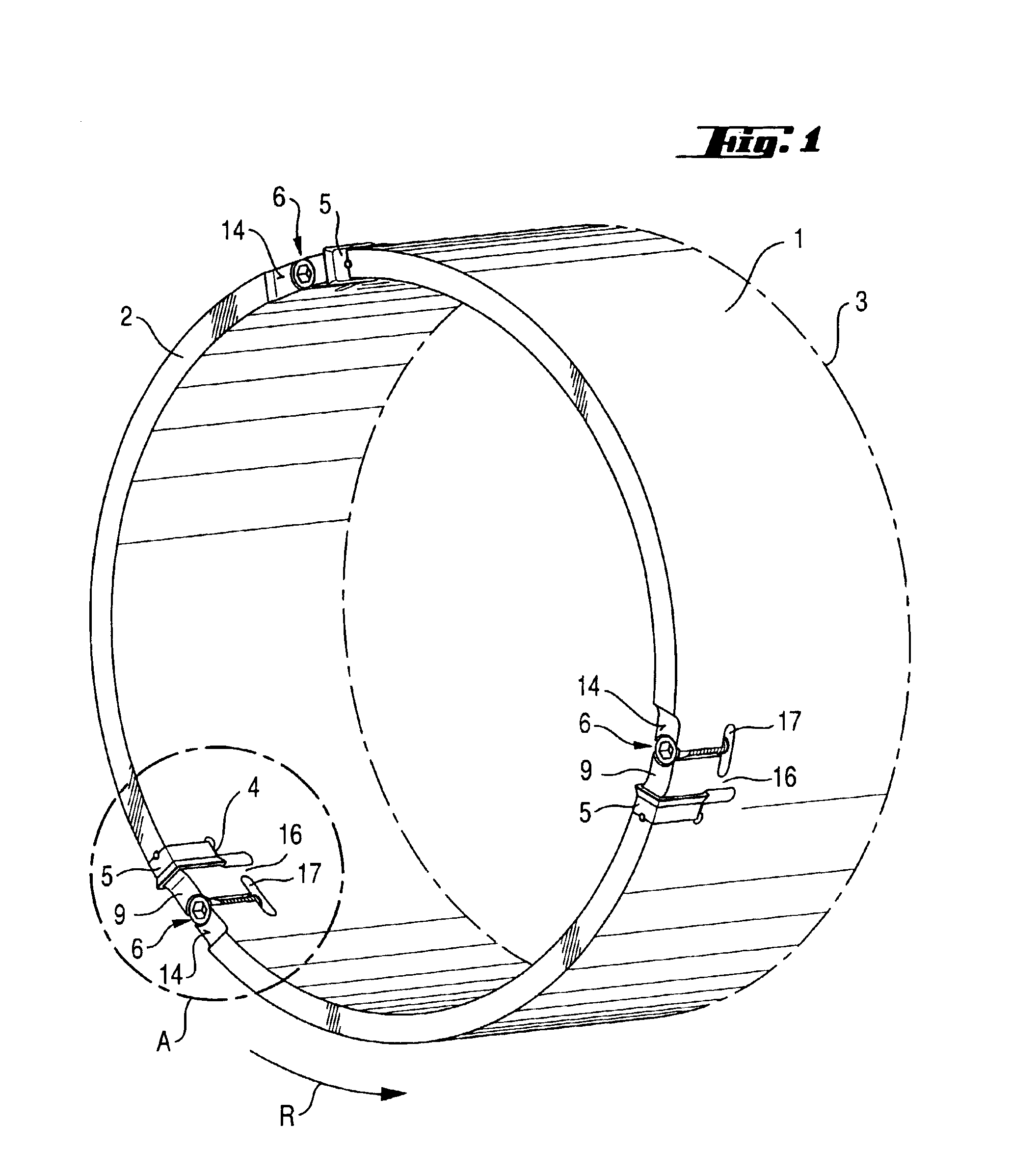
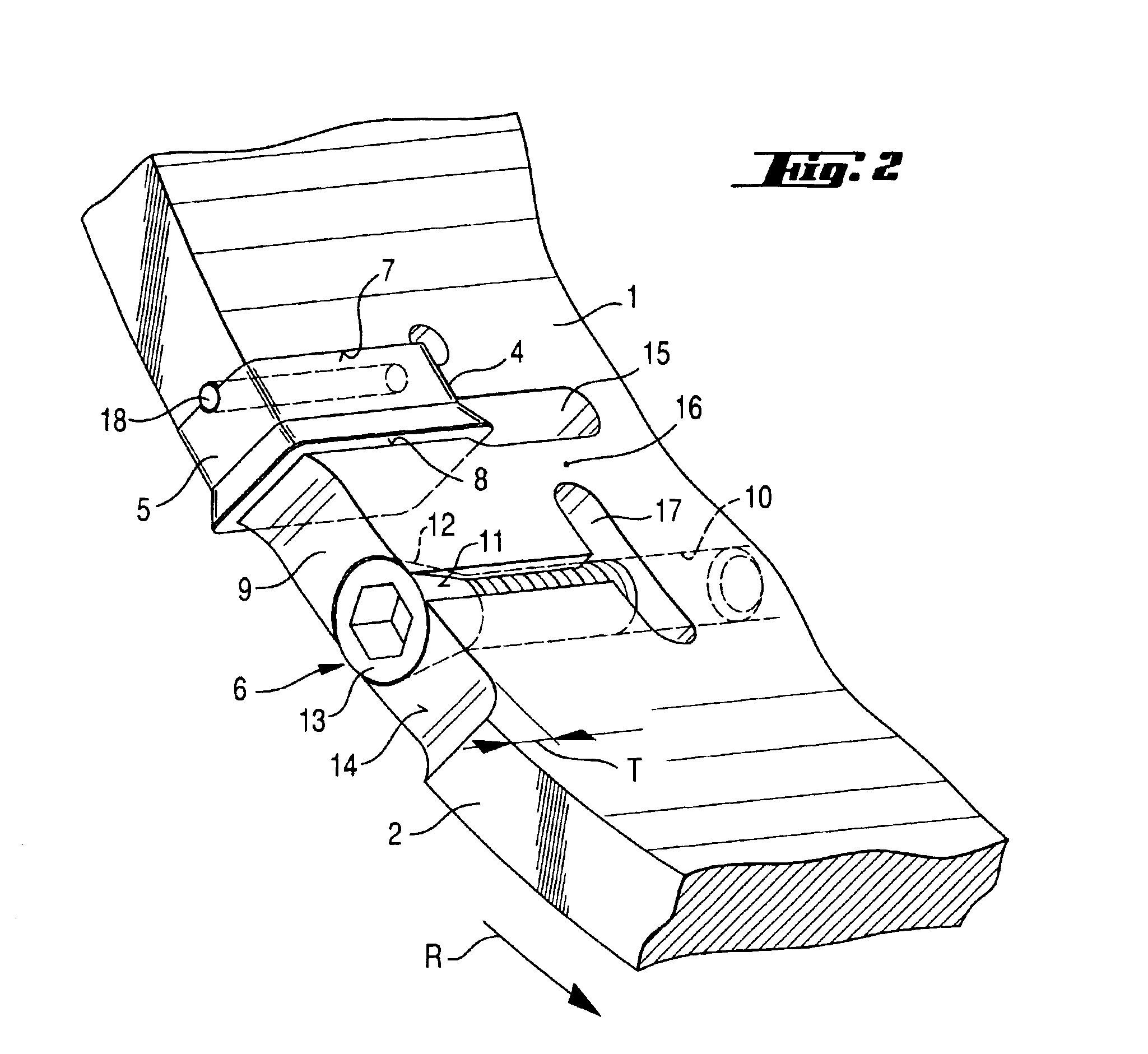
[0028]The present invention will now be explained in detail with reference to particular embodiments of the inventive cutting tool shown in FIGS. 1-3 which show a core bit (FIGS. 1-2) and a circular saw blade (FIG. 3). For simplicity sake, the same reference numerals are used in FIGS. 1-2 and FIG. 3.

[0029]A rotatable cutting tool, which is shown in FIGS. 1-3, has a receiving region 3 and a support region 1 having an end surface 2 remote from the receiving region 3. A plurality of recesses 4 extend partially over the support region in a direction toward the receiving regions 3. In each of the recesses 4, there is located a cutting element 5 which is secured by a locking element, e.g., in form of a tightening screw 6 displaceable substantially parallel to the longitudinal extent of the recess 4. Each recess 4 has a rigid stop surface 7 for the cutting element 5. The stop surface 7 is formed by the support region 1 and faces in a rotational direction R of the tool. Each recess 4 furthe...


PUM


Abstract

A rotatable cutting tool having s support region (1) with an end surface (2) and a plurality of recesses (4) extending from the end surface (2) and in which, respectively, a plurality of cutting elements (5) are arranged, with each recess having a rigid stop surface (7) for a cutting element (5) and faces in a rotational direction (R) of the tool, and a gripping surface (8) facing in a direction opposite the tool rotational direction (R) and cooperating with the cutting element, with the gripping surface (8) being displaceable by a respective locking element in the direction opposite the tool rotational direction.

Description

BACKGROUND OF THE INVENTION[0001]1. Field of the Invention[0002]The present invention relates to a rotatable cutting tool including a receiving region, a support region having an end surface remote from the receiving region and a plurality of circumferentially spaced from each other, recesses formed in the support region and extending from the end surface in a direction toward the receiving region, a plurality of cutting elements arranged in respective recesses, and a plurality of locking elements displaceable in a direction substantially parallel to a longitudinal extent of the recesses for securing respective cutting elements in the respective recesses.[0003]2. Description of the Prior Art[0004]U.S. Pat. No. 3,308,689 discloses a cutting tool having a tubular support region provided with a plurality of recesses which extend from the end surface of the support region in a direction toward a receiving region. In each of the recesses, there is located a cutting element formed of a ha...

Claims


Application Information

Patent Timeline
IPC IPC(8): B23B51/04B23C5/16B23C5/22
CPCB23B51/0433B23C5/2243B23B2205/02Y10T408/895Y10T407/1922Y10T407/194Y10T408/90987B23B51/0426
Inventor BLESSING, MATTHIASWANGER, WERNER
Owner HILTI AG
Why Eureka
Try Eureka