Continuously variable transmission

a transmission and variable technology, applied in the direction of gearing, cycle equipment, hoisting equipment, etc., can solve the problems of reducing durability, reducing the distance between the axes of driving and driving pulleys, and requiring a larger rotational force for operating the stroke mechanism, so as to shorten the distance, shorten the distance, and reduce the size of the transmission

Inactive Publication Date: 2005-06-07
DAIHATSU MOTOR CO LTD
View PDF15 Cites 18 Cited by
  • Summary
  • Abstract
  • Description
  • Claims
  • Application Information

AI Technical Summary

Benefits of technology

[0010]In the present invention, the rotational force of the motor is transmitted to the stroke mechanisms of both pulleys via the gear mechanism so as to shift the movable sheaves of both pulleys synchronously and axially in opposite directions to each other in relation to the fixed sheaves. Namely, the widths of the grooves of both pulleys alter oppositely to each other. The rotation angle of the motor is converted into the traveling distance of the movable sheaves in the axial direction by the stroke mechanism, such that the transmission ratio can be controlled to a proper ratio accurately.
[0021]The above described tension-adjusting device may preferably comprise a tension roller coming into pressure contact with the slack side of the belt from outside, a tensioner arm whose one end is swingably supported on the housing at a position outside of either of the pulleys in radial direction and whose other end has the tension roller attached thereto, and an urging means for swingingly urging the tensioner arm in such direction that the tension roller presses the belt. The tensioner arm may preferably be longer than the diameter of the pulley and curved along the outer periphery of this pulley. Further, the tensioner arm may preferably be arranged in such a way that the traveling locus of the axis for supporting the tension roller passes between the driving and driven pulleys. Since the tension roller presses the slack side of the belt from outside to generate proper tension, the contact areas of the belt wound around the pulleys are increased as compared with a case in which the belt is pressed from inside, thereby the transmission efficiency can be improved. By arranging the rotation fulcrum of the tensioner arm on the housing at a position outside of a pulley in radial direction, and by making the center in width of the tensioner arm substantially correspond to the center of the pulley in the axial direction, it becomes possible to support a central shaft of the tension roller at both ends thereof with the tensioner arm without inclination. As a result, the tension roller can contact with the belt in well-balanced condition.

Problems solved by technology

Nevertheless, this pressing force, being transmitted to the stroke mechanism via the belt and the movable sheave, exerts heavy loads on the stroke mechanism.
However, when such screw means is operated under a large axial force, the screw means is worn away fast, resulting in reduced durability.
Further, when such a large axial force is exerted on the stroke mechanism, a larger rotational force is required for operating the stroke mechanism.

Method used


Image

  • Continuously variable transmission
  • Continuously variable transmission
  • Continuously variable transmission

Examples


Embodiment Construction

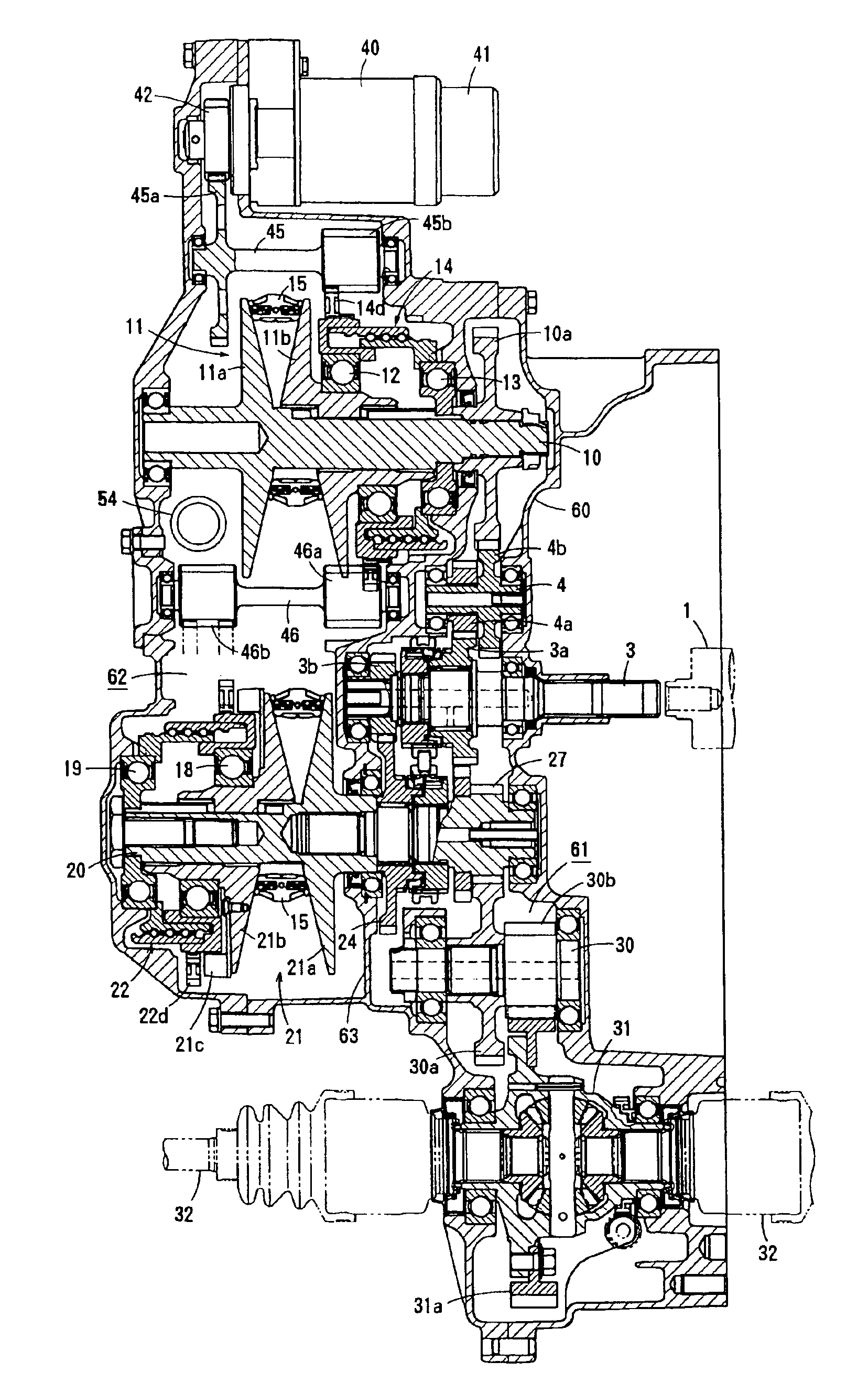
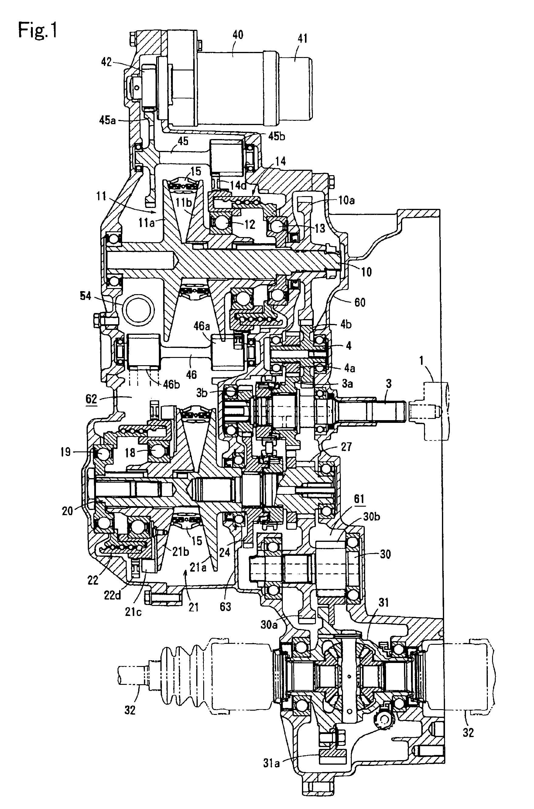
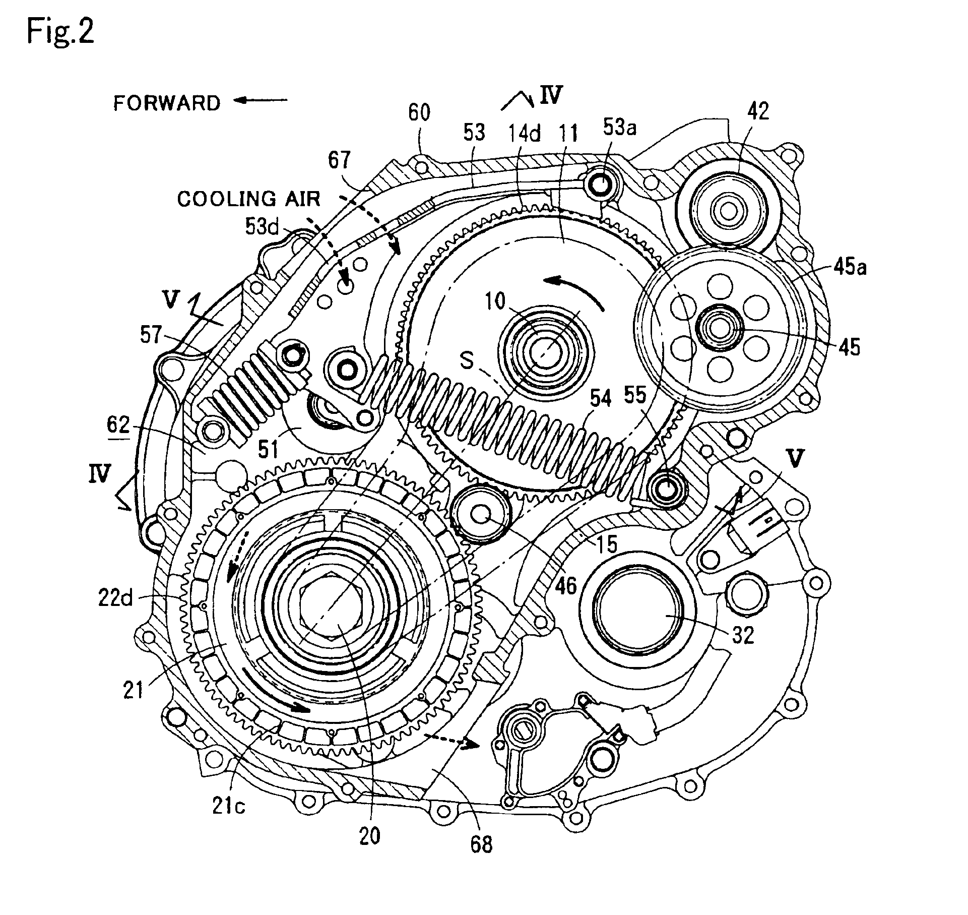
[0039]FIGS. 1 to 7 show a specific structure of a continuously variable transmission according to a first embodiment of the present invention, and FIG. 8 shows the skeleton structure thereof.

[0040]This continuously variable transmission, which is employed in a vehicle having a transversely mounted FF (front engine-front drive) system, generally comprises an input shaft 3 driven by an engine output shaft 1 via a starting clutch 2, a countershaft 4, a driving shaft 10 supporting a driving pulley 11, a driven shaft 20 supporting a driven pulley 21, a dry-type endless V belt 15 running around the driving pulley 11 and the driven pulley 21, a reduction shaft 30, output shafts 32 coupled with wheels, a ratio-changing motor 40, a tension-adjusting device (tensioner) 50 and the like. The input shaft 3, the countershaft 4, the driving shaft 10, the driven shaft 20, the reduction shaft 30 and the output shafts 32 are arranged non-coaxially and in parallel with each other.

[0041]Though the star...


PUM


Abstract

A continuously variable transmission including a driving pulley, a driven pulley, an endless dry-type belt wound around both pulleys, a tension-adjusting device for pressing the slack side of the belt to generate belt tension, stroke mechanisms provided on both pulleys for axially shifting the movable sheaves, a ratio-changing motor, and a gear mechanism for transmitting the rotational force generated by the motor to both stroke mechanisms in such a way that the movable sheaves of both pulleys can be shifted synchronously and axially oppositely in relation to the fixed sheaves. With this arrangement, the belt is prevented from slipping, the transmission ratio can be controlled precisely and stably, and the shift-response of this transmission can be improved. The motor can be reduced both in its size and its consumption of electric power.

Description

BACKGROUND OF THE INVENTION[0001]1. Field of the Invention[0002]The present invention relates to a continuously variable transmission, and more particularly, it relates to a V belt continuously variable transmission for an automobile.[0003]2. Description of the Related Art[0004]Generally, a continuously variable transmission has been proposed, as described in Japanese Laid Open Patent No. 64-58848 (1989) for example, which includes a driving pulley, a driven pulley, a metallic belt placed around the driving and driven pulleys, a pressure regulating mechanism attached to at least one of those pulleys for exerting an axial force corresponding to the applied torque, and stroke mechanisms (actuator mechanisms) attached to the driving and driven pulleys respectively for moving the movable sheaves in the axial direction, and a shifting device for operating the stroke mechanisms at the time of changing the transmission ratio.[0005]This shifting device includes a motor, an operating shaft h...

Claims


Application Information

Patent Timeline
Patent Type & Authority Patents(United States)
IPC IPC(8): F16H9/02F16H7/08F16H61/662F16H37/02F16H9/18F16H61/66F16H7/12F16H63/06F16H63/02
CPCF16H7/08F16H7/1281F16H9/18F16H37/027F16H61/66272Y10T74/19167F16H63/062F16H2007/0806F16H2007/0808
Inventor MURAKAMI, HISAYASUTEMMA, YASUYUKITANAKA, MASAHIRO
Owner DAIHATSU MOTOR CO LTD
Why Eureka
Try Eureka