Transverse transmission device of weft paving trolley of tricot machine

A technology of weft laying trolley and transmission device, which is applied in warp knitting, textiles, papermaking, knitting, etc., and can solve the problems of different degrees of wear, heavy force, and loud noise

Active Publication Date: 2009-06-03
江苏润源控股集团有限公司
View PDF0 Cites 6 Cited by
  • Summary
  • Abstract
  • Description
  • Claims
  • Application Information

AI Technical Summary

Problems solved by technology

The traversing transmission device of this structure, after running for a certain period of time, due to the severe wear and different degrees of wear of the gear and the rack, and the lack of rigidity of the output shaft of the motor, when the gear rolls along the rack, the gear rolls along the rack. Up and down and / or forward and backward movement occurs on the strip, which greatly affects the transmission accuracy, resulting in unstable lateral movement speed of the weft laying trolley, and improper movement of the rake needle, thus failing to meet the accuracy requirements required for lateral movement; especially in order to increase When the weft laying time is reduced to increase the traversing speed due to the output, this kind of movement is more serious, which greatly limits the traversing speed and greatly reduces the production efficiency. In addition, the noise of the gear rolling is also large, which affects Operator's health
Another structure of weft laying trolley traversing transmission device is designed to overcome the shortcomings of the above structure. The transmission mode composed of strips; the annular synchronous transmission belt is located between the synchronous pulley and the rack with its toothed surface facing outwards, and in the annular synchronous transmission belt and on both lateral sides of the synchronous pulley, tensioner pulleys are respectively arranged to make synchronous The upper part of the transmission belt meshes with the synchronous pulley, and the lower part meshes with the rack; when doing lateral movement, the motor drives the synchronous pulley to rotate, and at the same time drives the ring-shaped synchronous transmission belt to rotate, and makes the synchronous transmission belt mesh along the toothed surface of the rack. In this way, the traversing support seat and the weft laying trolley can move laterally along the length direction of the guide rail; the traversing transmission device with this structure has high transmission precision, fast transmission speed, greatly improved production efficiency, and can meet production requirements. , but due to the large force and serious wear of the synchronous transmission belt and the rack, fracture accidents often occur, once or twice a month or even more, and each repair takes several hours to complete, so It seriously affects the continuous production of fabrics, and at the same time increases the maintenance cost, and because the price of the synchronous transmission belt is high, it increases the production cost

Method used


Image

  • Transverse transmission device of weft paving trolley of tricot machine
  • Transverse transmission device of weft paving trolley of tricot machine
  • Transverse transmission device of weft paving trolley of tricot machine

Examples


Embodiment Construction

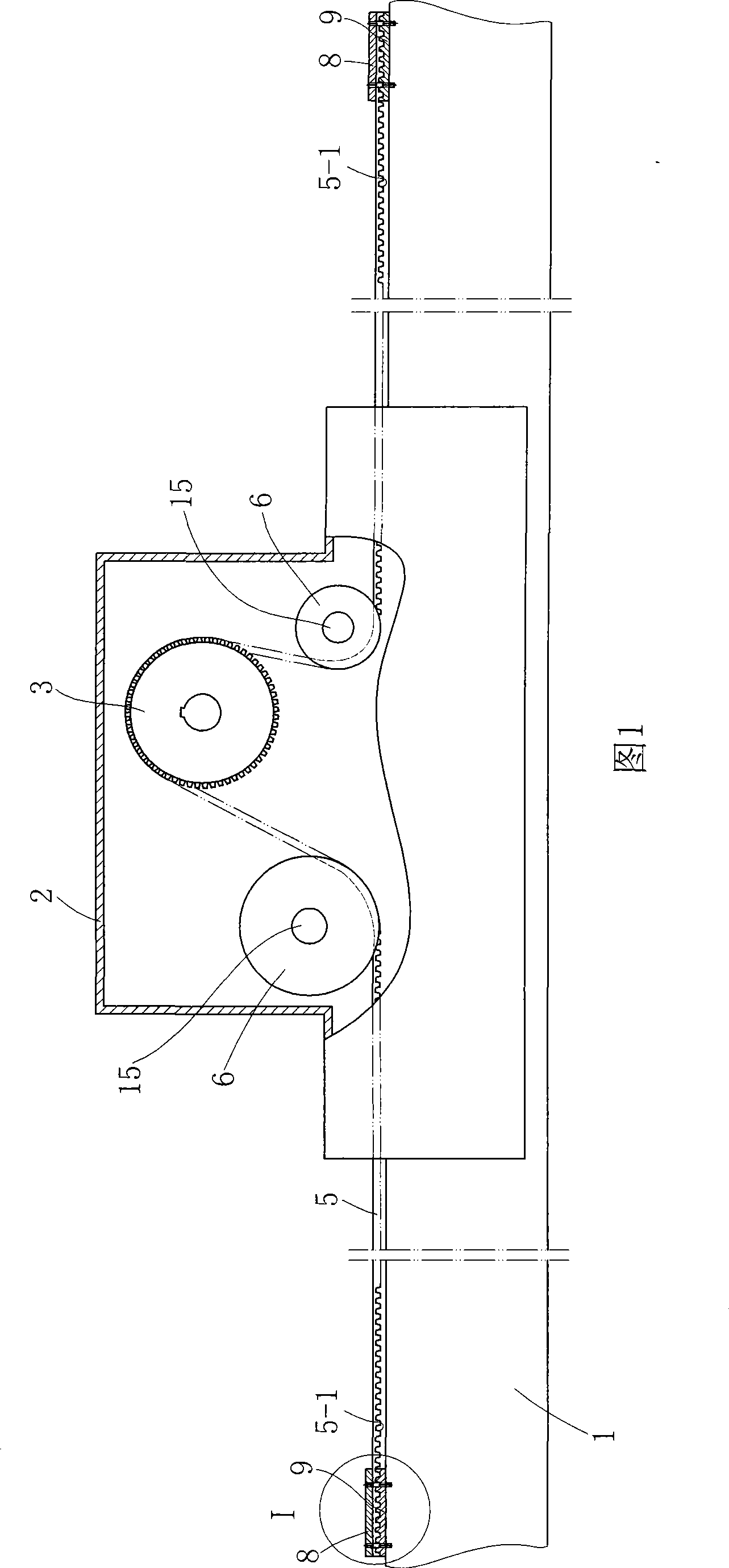
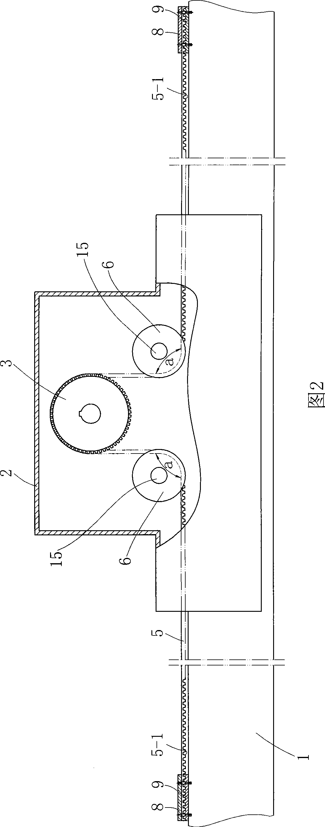
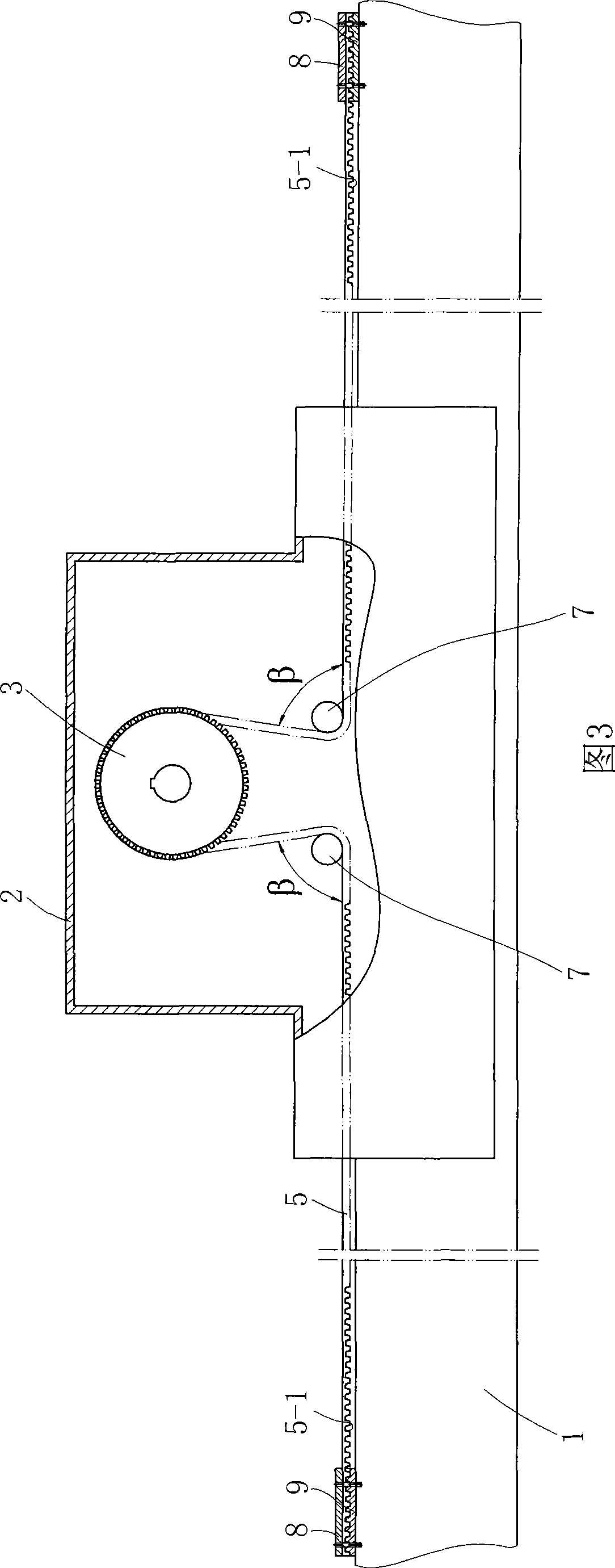
[0015] See Figures 1, 2, 3 and Figure 5 The traversing transmission device of a warp knitting machine weft laying trolley shown includes a traversing support seat 2 that rolls or slides with the beam guide rail 1 of the warp knitting machine and a synchronous pulley 3 placed in the traversing support seat 2, The drive device 4 is fixedly connected to the traversing support base 2, and the synchronous pulley 3 is driven to rotate by the drive device 4, as Figure 5 As shown, the driving device 4 used in the present invention is a servo motor; a synchronous transmission belt 5 is arranged on the upper part of the guide rail 1 along its length direction, and the toothed surface 5-1 of the synchronous transmission belt 5 is opposite to the upper surface of the guide rail 1 , and its two ends pass through the lateral sides of the traversing supporting base 2 and are fixedly connected with the guide rail 1, and the synchronous transmission belt 5 located in the traversing supportin...


PUM


Abstract

The invention discloses a transverse transmission device of a weft paving trolley, which comprises a transverse supporting base matched with the cross beam of a tricot machine in a rolling or sliding manner and a timing belt pulley arranged in the transverse supporting base. A drive device is fixedly connected to the transverse supporting base; the timing belt pulley is driven to rotate by the drive device; a synchronous transmission belt is arranged at the upper part of a guide rail in the length direction, and the gear-shaped surface of the synchronous transmission belt and the upper surface of the guide rail are oppositely arranged, and both ends of the synchronous transmission belt pass through the two transverse sides of the transverse supporting base respectively and are fixedly connected with the guide rail; and the synchronous transmission belt positioned in the transverse supporting base is meshed and matched with the timing belt pulley. Synchronous belt guide pulleys are symmetrically arranged on two transverse sides of the timing belt pulley; and a wrapping angle of the synchronous transmission belt formed in the connecting position of the synchronous belt guide pulleys and the synchronous transmission belt is smaller than or equal to 90 degrees. The invention has the advantages of high driving accuracy, damage resistance, long service life and low noise, and has good commercial prospect.

Description

technical field [0001] The invention relates to a transmission device for a weft laying trolley in a weft laying mechanism of a warp knitting machine, in particular to a traversing transmission mainly used for a weft laying trolley in a multiaxial warp knitting machine. Background technique [0002] In the existing multi-axial warp knitting machine for weaving weft-inserted warp-knitted fabrics, there are roughly two types of weft-laying trolley traversing transmission devices used. Seat, the gear set in the traversing support seat, the gear rack meshed with the gear and the motor fixedly connected to the traversing support seat, the weft laying trolley is fixedly connected to the longitudinal arrangement between the beams of the warp knitting machine On the beam slider, the longitudinal beam is fixedly connected with the traversing support seat, and the rack made of metal materials such as aluminum alloy is laid on the upper surface of the guide rail along the length direct...

Claims


Application Information

Patent Timeline
Patent Type & Authority Applications(China)
IPC IPC(8): D04B27/08
Inventor 王占洪肖叶黄骏
Owner 江苏润源控股集团有限公司
Why Eureka
Try Eureka