
Method for cleaning charged particles from an object

a technology for cleaning particles and objects, applied in the direction of cleaning using liquids, drying machines with progressive movements, furnaces, etc., can solve the problems of difficult dislodging of particles using, accumulating dirt and other undesirable particles, recyclable cameras, etc., and achieves the effect of simple use and cost-effective construction and operation

Inactive Publication Date: 2005-06-07
EASTMAN KODAK CO
View PDF13 Cites 18 Cited by
  • Summary
  • Abstract
  • Description
  • Claims
  • Application Information

AI Technical Summary

Benefits of technology

[0013]It is another object of the invention to provide an apparatus that removes contaminant particles from product having generally irregular, undulating, surface features so as to enable the product to be refurbished and returned to the stream of commerce.
[0014]Yet another object of the invention is to provide an apparatus and method for disposing of particles dislodged from the generally irregular, undulating surface features of product being cleaned so as to prevent cross-contamination of other product.
[0018]The above invention has numerous advantages over existing developments, including: it overcomes the limitations of conventional ionization and air knife cleaners to remove electrostatically bonded particles such as dust from generally, irregular, undulating surface features; it operates automatically without direct operator intervention; it is cost effective to construct and operate; and, it is simple to use.

Problems solved by technology

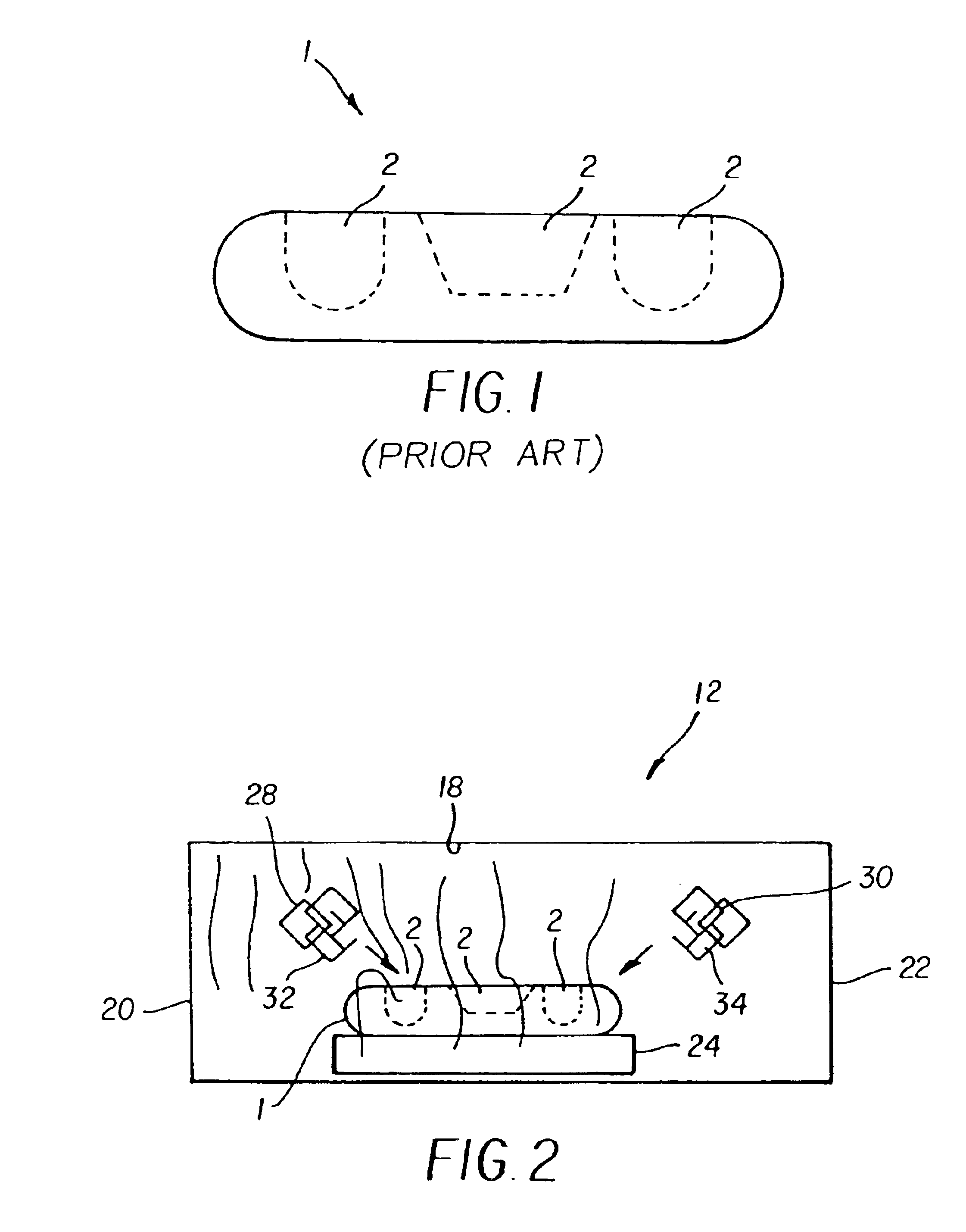
Referring to FIG. 1, objects 1 having generally irregular or undulating surface features 2, e.g., non-planar surfaces, present a special challenge to clean because such surfaces have a plurality of features 2 that makes it difficult to dislodge particles using existing techniques.
Similarly, recyclable cameras, which are returned to the manufacturer for refurbishing, accumulate dirt and other undesirable particles that must eventually be cleaned during refurbishing.
Further, camera storage and the recycling process can expose the re-useable components of the camera to fibers and particles large enough to enter the film exposure window resulting in shadow images of these particles and fibers on the customer's pictures.
A significant shortcoming of these existing cleaning systems is that they are much too inefficient to operate.
This typically results in large volumes of dust-laden air being drawn from the surrounding room air into the cleaning device.
As a result, there is a high risk of re-contaminating the cameras after cleaning.
This design was also unsatisfactory, as the air nozzles did not provide enough force to dislodge particles and neutralize the electrostatic bonding force between the particles and the electric field intensities on the camera.
More damaging, the transvector was drawing a large volume of room air into the chamber, and because of the directionality of the air from the nozzles to the transvector, large volumes of dirty air was being discharged down the conveyor belt.
Objects having irregular surface features, i.e., three dimensional or surfaces having protuberances such as camera components, do not allow intimate enough location for effective cleaning, and present too many angles to an air knife to be effective.
A major shortcoming of each of these cleaning devices is that they have proven woefully inadequate for cleaning objects, like camera components, having irregular features (non-planar) and surfaces.

Method used


Image

  • Method for cleaning charged particles from an object
  • Method for cleaning charged particles from an object
  • Method for cleaning charged particles from an object

Examples


example 1

[0043]This example demonstrates that for the apparatus 10 of the invention, an air knife pressure of at least 20 psi yields extraordinary cleaning of both fibers and plastic contaminants from the object being cleaned.

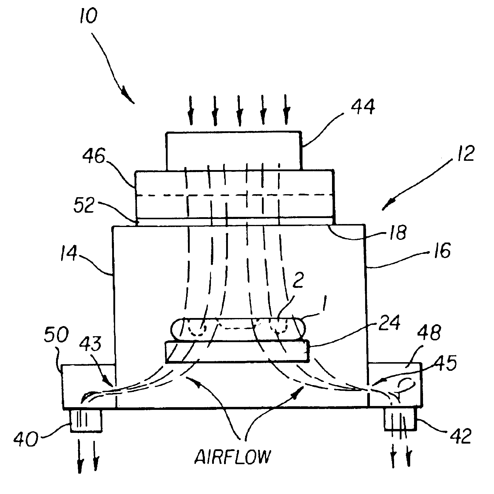
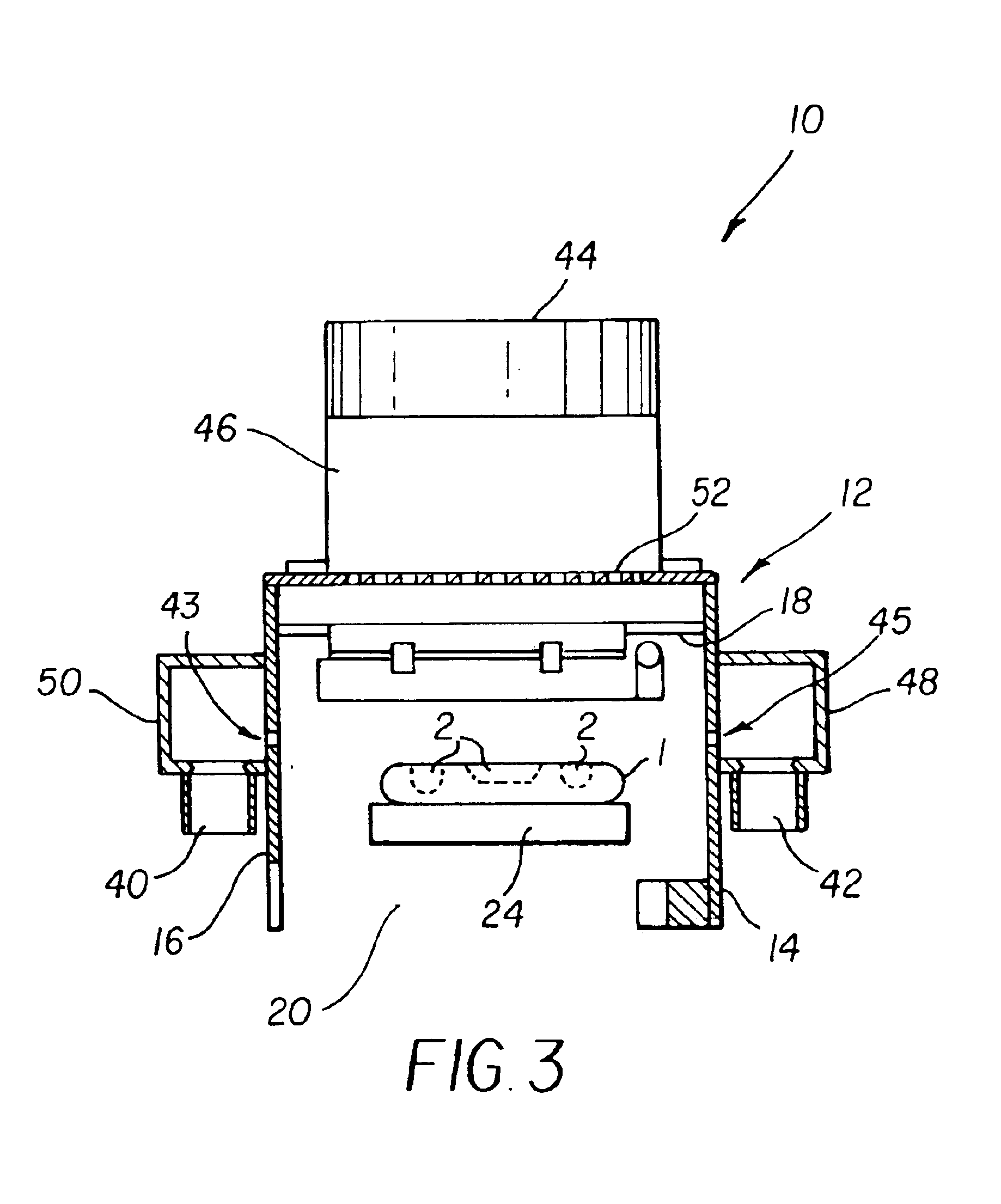
[0044]Apparatus 10 (refer to FIGS. 2 and 3) of the invention for cleaning irregularly shaped features 2 of objects 1 was tested for electric field intensity and particle removal efficiency. A rough measure of the electric field intensity was made using an electrostatic fieldmeter, such as a Simco Hand-E-Stat™ meter. The test sequence consisted of first tribo charging the object 1 being cleaned, such as a camera body component, with a color (e.g., blue) cotton cloth, to approximately −2000 volts / cm. A piece of polystyrene is then scraped over the camera component, adding plastic shavings or skivings onto the generally irregular, undulating surface features 2, including, for instance, in the film wells and lens baffle. Using the Simco meter, the electric field intensity i...

example 2

[0050]This example demonstrates that consistent cleaning efficiency, not possible in conventional cleaners, is provided by the positive pressurization requirement in apparatus 10 of the invention.

[0051]Referring to Table 2, in order to determine if the pressurization system was needed, the test was repeated with the fan shut off. While no air was forced through the filter and screen, the downward direction resulting from the combination of the air knife pressures and the exhaust slots drew air though the fan and filter, into the chamber:

[0052]

TABLE IItop fan offair curtainE-field beforeE-field afterfiberplasticpsikv / cm.kv / cm.removalremoval82.040.181182.960.192182.030.1511122.430.1631122.320.1241122.170.1232153.320.1343151.880.0742152.850.1343202.260.0544201.850.0554202.070.0443242.150.0444242.020.0333242.510.0623282.540.0254282.320.0754282.780.0445

[0053]According to Table II, the results indicate that without the pressurization (see Table I), the cleaning efficiency is erratic, part...

example 3

[0054]In this example it is demonstrated that cleaning efficiency of apparatus 10 can be easily optimized as a function of enclosure pressure.

[0055]Referring to Table III, tests were performed to determine the optimum cleaning efficiency with varying chamber pressures. To change the amount of air directed downwardly into the cleaning chamber or partial enclosure 12, two perforated plates were selected that restrict the air flow more than the initial perforated plate. The original perforated plate allowed greater than 50% of the filtered air to pass through into the chamber.

[0056]According to Table III, the first perforated plate to be tested restricts the air flow to 26% of the fan capacity:

[0057]

TABLE IIIairknifeE-field beforeE-field afterrankrankpressurekv / cm.kv / cm.fibersplastic122.561.2811cleaned emitter points122.630.2631152.580.3853152.180.3231152.360.3833203.170.2633252.1 0.2432252.570.2844301.990.2855

[0058]According to Table IV below, a second perforated plate tested restrict...


PUM

PropertyMeasurementUnit
Electric potential / voltageaaaaaaaaaa
Lengthaaaaaaaaaa
Lengthaaaaaaaaaa

Abstract

An apparatus and method for cleaning objects having generally irregular surface features, such as reloadable photographic cameras, has a partial enclosure having opposing side walls, and a top wall joining the opposing side walls. An air ionizing element composed of an ion emitter and an air knife is arranged in the enclosure for electrostatically neutralizing the object with ions entrained in a curtain-like stream of air directed onto the object.

Description

CROSS-REFERENCE TO RELATED APPLICATIONS[0001]This is a divisional of application Ser. No. 09 / 624,627 filed Jul. 24, 2000, now U.S. Pat. No. 6,543,078, issued Apr. 8, 2003.The present application is related to U.S. application Ser. No. 09 / 624,628, filed Jul. 24, 2000 (now abandoned), by Thomas Albano, et al., and entitled, “Apparatus For Neutralizing Electrostatic Charges On Generally Irregular, Undulating Surfaces;” and U.S. Pat. No. 6,490,746, issued Dec. 10, 2002.FIELD OF THE INVENTION[0002]The invention relates generally to an apparatus and method for cleaning particles adhered to an object. More specifically, the invention concerns an apparatus and method for cleaning particles, e.g., dust, from generally irregular, undulating, surface features of objects or recyclable product so that the product can be refurbished and returned to the stream of commerce.BACKGROUND OF THE INVENTION[0003]Apparatus for cleaning charged particles, such as dust, from surfaces of objects are well know...

Claims


Application Information

Patent Timeline
IPC IPC(8): B08B6/00
CPCB08B6/00B08B5/04B08B5/02
Inventor ERNST, GERARD W.ALBANO, THOMASSMITH, DEAN L.POHL, KLAUS R.
Owner EASTMAN KODAK CO
Learn More