Method of driving liquid crystal display

display technology, applied in the field of driving a liquid crystal display, can solve the problems of insufficient response time of liquid crystal or liquid crystal display, no significant increase in brightness over what can be achieved, etc., and achieve the effect of less driving time and increased brightness

Inactive Publication Date: 2005-06-07
LG DISPLAY CO LTD
View PDF7 Cites 10 Cited by
  • Summary
  • Abstract
  • Description
  • Claims
  • Application Information

AI Technical Summary

Benefits of technology

[0016]Accordingly, it is an advantage of the present invention to provide a method of driving a liquid crystal display for increasing brightness thereof.
[0017]In order to achieve these and other advantages of the invention, a method of driving a liquid crystal display device according to the present invention includes the steps of arranging two color filters having spectrums different from each other; arranging two back lights having spectrums different from each other; and turning on and off, in turn, said two back lights to realize full color of a picture with only two frames.
[0018]In another aspect of the present invention, said step of turning on and off, in turn, said two back lights to realize full color of a picture with only two frames includes realizing color by mixing spatially for two colors; and realizing color through mixing by time for a remained color.
[0019]In another aspect of the present invention, of said two color filters, a first color filter is a color filter of 2 colors which has a light of red and blue (R+B), and a second color filter is a color filter of 2 colors which has a light of green and blue (G+B).
[0020]In another aspect of the present invention, of said two frames, a first frame has a back light of two colors with a light of red and green (R+G), and a second frame has a back light of blue.
[0021]In another aspect of the present invention, an area of said frame having said back light of blue has less driving time than an area of said frame having said back light of two colors with a light of red and green (R+G).

Problems solved by technology

No significant increase in brightness is gained over what can be achieved conventionally because a limit is reached in trying to decrease the time, Td, for writing data when driving a liquid crystal display.
Furthermore, the time, Tbl, during which the back light can be turned on, is reduced if the liquid crystal response time is increased so that the response time of the liquid crystal or the brightness of the liquid crystal display become inadequate.

Method used


Image

  • Method of driving liquid crystal display
  • Method of driving liquid crystal display
  • Method of driving liquid crystal display

Examples


Embodiment Construction

[0036]Reference will now be made in detail to the principles of the present invention, an example of which is illustrated in the accompanying drawings.

[0037]The principles of the present invention are explained with reference to FIGS. 3 to 7.

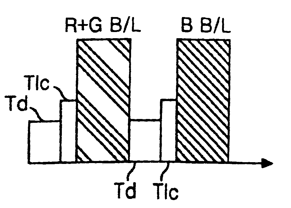
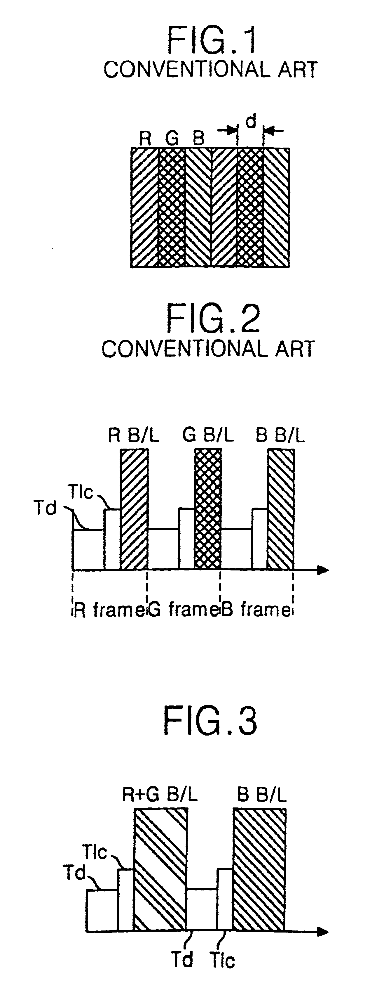
[0038]FIG. 3 represents time characteristics of a method of driving a liquid crystal display according to the present invention.

[0039]Referring to FIG. 3, in the present invention, a frame consisting of two back lights consists of a frame where a red and green (R+G) back light is turned on and a frame where a blue back light is turned on. Because a screen consists of two frames, the time during which each back light is turned on in a frame becomes longer than if three back lights were being used. To describe in more detail, formula 1, has been changed such that Tt=2Tw′+Tbl′. Herein, ‘2’ represents the number of the frames used in present invention. If the data writing time, Td, and the liquid crystal response time, Tlc, are equal (that is, Tw′=T...


PUM

PropertyMeasurementUnit
timeaaaaaaaaaa
driving timeaaaaaaaaaa
data writing timeaaaaaaaaaa

Abstract

This invention relates to a method of driving a liquid crystal display that is adaptive for displaying pixel color with high brightness in a liquid crystal cell. The method of driving a liquid crystal display having a color filter and a back light, includes arranging in turn two color filters which have spectrums different from each other, and arranging two back lights which have spectrums different from each other. In the method, by lengthening the time during which a back light can be turned on when driving a liquid crystal display, transmissivity of light is increased so that the color of a liquid crystal cell can be displayed in high brightness.

Description

[0001]This application claims the benefit of Korean Patent Application No. P20007-6845, filed Dec. 15, 2000, which is hereby incorporated by reference in its entirety as if fully set forth herein.BACKGROUND OF THE INVENTION[0002]1. Field of the Invention[0003]This invention relates to a method of driving a liquid crystal display, and more particularly to a method of driving a liquid crystal display that is adaptive for displaying pixel color with increased brightness in a liquid crystal cell.[0004]2. Description of the Related Art[0005]Generally, an active matrix liquid crystal display (LCD) uses a thin film transistor (TFT) as a switching device to display a moving picture. Since the LCD is able to provide a product having a smaller dimension than a Brown tube or cathode Ray Tube, it has been widely used in various applications of personal computers, notebook computers, office automation equipment such copy machines, etc., and portable equipment such as a cellular phones, pagers, e...

Claims


Application Information

Patent Timeline
Patent Type & Authority Patents(United States)
IPC IPC(8): G09G3/36G09G3/34G02F1/133
CPCG09G3/3413G09G3/3607G09G2310/0235G09G2300/0452G02F1/133
Inventor SON, HYEON HO
Owner LG DISPLAY CO LTD
Why Eureka
Try Eureka