Pattern writing apparatus and pattern writing method

a pattern writing and pattern technology, applied in the field of pattern writing apparatus and pattern writing method, can solve the problems of difficult to drive the spatial light modulator at higher speed, limited what we can do to shorten, and high pattern writing speed, and achieve the effect of high speed

Inactive Publication Date: 2005-06-07
DAINIPPON SCREEN MTG CO LTD
View PDF29 Cites 32 Cited by
  • Summary
  • Abstract
  • Description
  • Claims
  • Application Information

AI Technical Summary

Benefits of technology

[0010]The present invention is directed to a pattern writing apparatus for writing a pattern on a photosensitive material, and an object of the present invention is to write a fine pattern at high speed.
[0012]The present invention allows multiple light irradiation on the photosensitive material with efficiency, thereby achieving high-speed pattern writing.
[0013]According to a further preferred embodiment of the present invention, light irradiation of an irradiation region is controlled to be OFF before relative movement of the irradiation region group by a distance equal to n times the writing pitch is finished after light irradiation of the irradiation region is controlled to be ON. This improves writing resolution.
[0014]According to a further preferred embodiment of the present invention, each element of a light modulating element group is a micromirror that changes its position. The scanning mechanism accelerates high-speed pattern writing by continuously moving the irradiation region group.

Problems solved by technology

However, there are technical limitations to what we can do to shorten such times. Thus, it is not easy to drive the spatial light modulator at higher speed and thereby to speed up pattern writing by exposure.
However, addressing and writing data into the blocks is generally performed on line by line; therefore, when this DMD is employed in the technique shown in FIG. 1, data must be written into every block containing part of the main scan mirrors and the interpolation main scan mirrors, which makes it difficult to achieve high speed pattern writing.

Method used


Image

  • Pattern writing apparatus and pattern writing method
  • Pattern writing apparatus and pattern writing method
  • Pattern writing apparatus and pattern writing method

Examples


Embodiment Construction

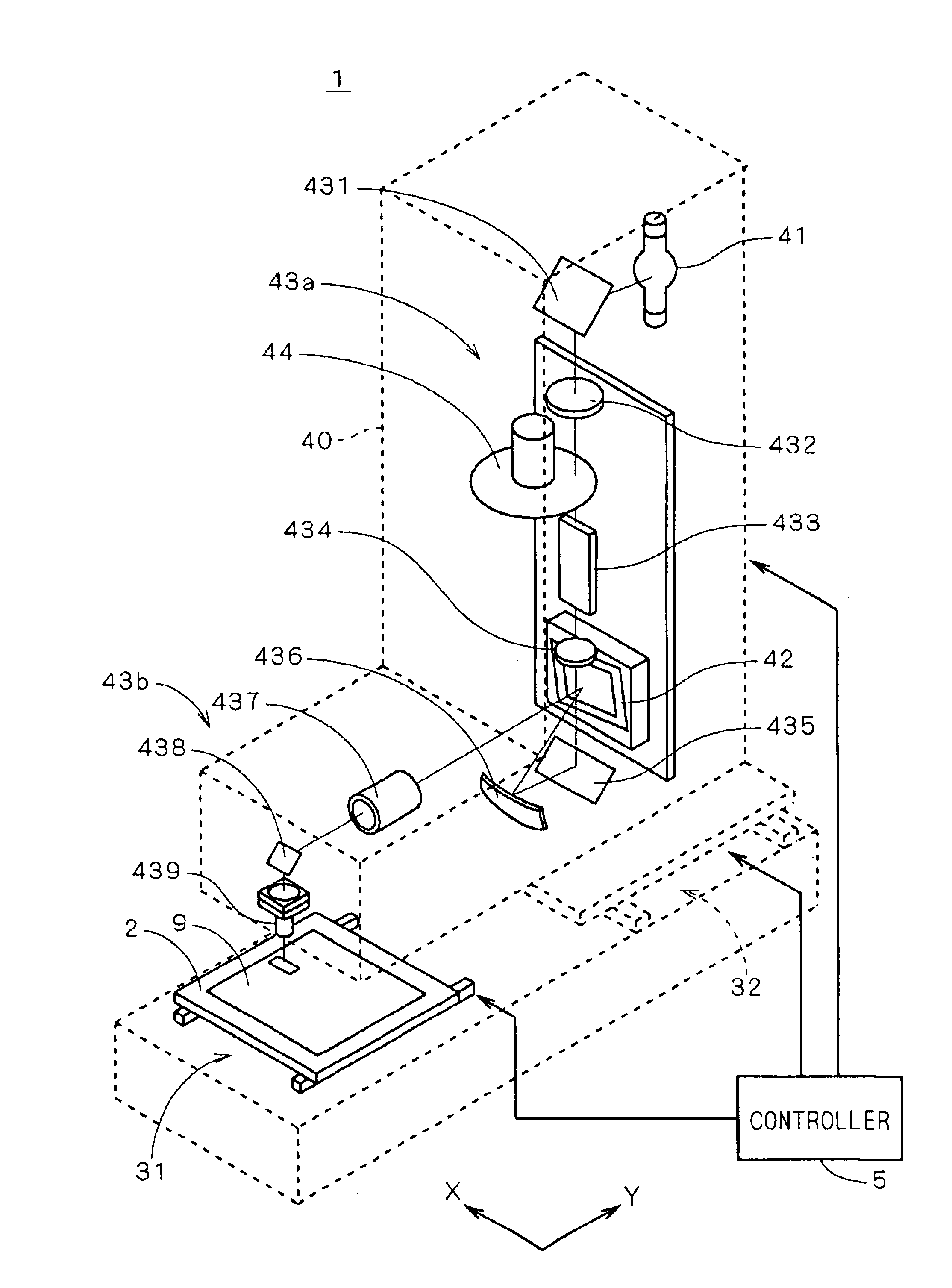
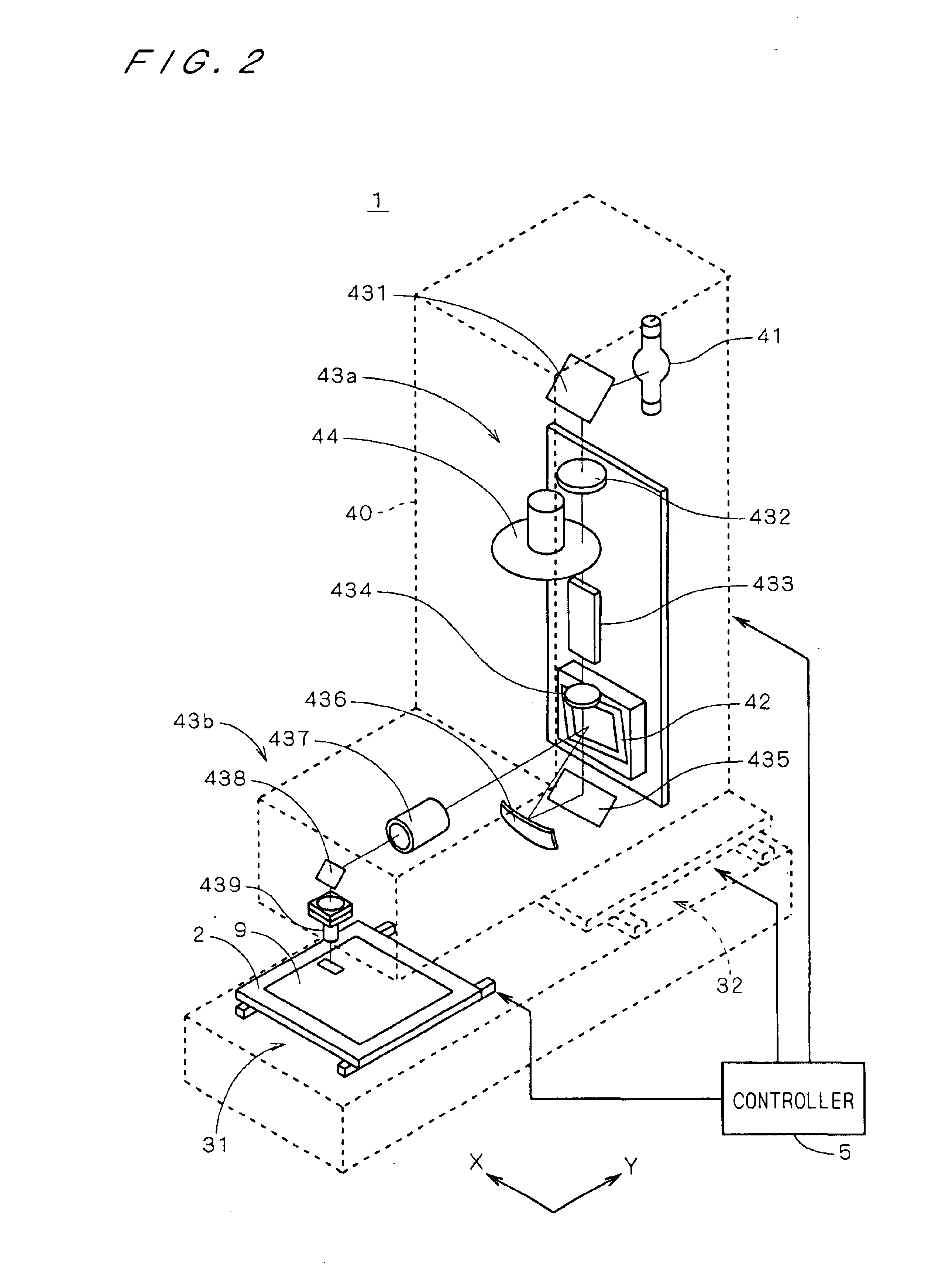
[0039]FIG. 2 is a diagram illustrating the structure of a pattern writing apparatus 1 according to a first preferred embodiment of the present invention. In FIG. 2, part of the apparatus is shown by dashed lines for illustration of the internal structure of the apparatus. The pattern writing apparatus 1 comprises a stage 2 holding a substrate 9 on which a resist film is formed, a stage moving mechanism 31 for moving the stage 2 in the Y direction in FIG. 2, a head 40 functioning as a light irradiating part which emits a light beam toward the substrate 9, a head moving mechanism 32 for moving the head 40 in the X direction in FIG. 2, and a controller 5 connected to the stage moving mechanism 31, the head 40 and the head moving mechanism 32.

[0040]The head 40 includes a light source 41 which is a lamp for emitting light and a DMD 42 having a micromirror group arrayed in a lattice arrangement, wherein the micromirror group reflects a light beam from the light source 41 to provide a two-...


PUM

PropertyMeasurementUnit
angle of incidenceaaaaaaaaaa
widthaaaaaaaaaa
widthaaaaaaaaaa

Abstract

A pattern writing apparatus for writing a pattern on a photosensitive material comprises a head provided with a DMD having a micromirror group which spatially modulates reflected light. Light from the micromirrors of the DMD are directed to irradiation regions (61) on the substrate, respectively. The irradiation regions (61) are moved over the substrate with movement of the substrate relative to the head. The DMD is provided within the head so that the direction of arrangement of the irradiation regions (61) is tilted relative to the main scanning direction, and a center-to-center distance (L1) along the sub-scanning direction between two adjacent irradiation regions (61) arranged in the main scanning direction is made equal to a pitch (P1) of writing cells (620) on the substrate with respect to the sub-scanning direction. ON / OFF control of light irradiation of each irradiation region is performed each time the irradiation regions 61 move a distance equal to twice a pitch (P2).

Description

CROSS-REFERENCE TO RELATED APPLICATION[0001]This application is a continuation-in-part of application Ser. No. 10 / 394,261, filed Mar. 24, 2003 abandoned.BACKGROUND OF THE INVENTION[0002]1. Field of the Invention[0003]The present invention relates to an apparatus and method of writing a pattern by light irradiation to a photosensitive material.[0004]2. Description of the Background Art[0005]Conventionally well known are techniques for applying a light beam modulated by a spatial light modulator such as a digital micromirror device (DMD) onto a photoresist film formed on a substrate such as a semiconductor substrate or a printed circuit board.[0006]Japanese Patent Application Laid-open No. 62-21220 discloses a technique for writing a fine pattern by applying a light beam which is spatially modulated by a micromirror group of a DMD onto a photosensitive material and by moving the photosensitive material and controlling a signal given to the DMD every time the photosensitive material pa...

Claims


Application Information

Patent Timeline
Patent Type & Authority Patents(United States)
IPC IPC(8): G03F7/20H01L21/027
CPCG03F7/70283G03F7/70558G03F7/70358G03F7/70466G03F7/70291G03F7/2051G03F7/20
Inventor SHIROTA, HIROYUKIKUWABARA, AKIRA
Owner DAINIPPON SCREEN MTG CO LTD
Why Eureka
Try Eureka