Paralleled power factor correcting AC-to-DC converters with improved current balance

a technology of current balance and power factor, applied in the field of parallel power supply, can solve the problems of internal impedance and internal impedance of the various power supply

Inactive Publication Date: 2005-06-07
LOCKHEED MARTIN CORP
View PDF10 Cites 35 Cited by
  • Summary
  • Abstract
  • Description
  • Claims
  • Application Information

AI Technical Summary

Benefits of technology

[0012]In an advantageous embodiment of this aspect of the invention, each of the output return current equalizing impedances comprises resistance means. In a preferred embodiment of this aspect of the invention, the power factor correcting AC-to-DC switching converter units are boost power factor correcting AC-to-DC switching converter units. In a more preferred embodiment of this aspect of the invention, a controllable path is coupled to the source of pulsating direct voltage and to the load, for tending to charge a capacitive component of the load at turn-on, and for ceasing the charge after turn-on. The controllable path may include a controllable switch, where the controllable switch may include a unidirectional current conducting device which conducts when the pulsating direct voltage is greater than the voltage on the capacitive component and which ceases conduction when the pulsating direct voltage is less than the voltage on the capacitive component. In one particularly advantageous version of this aspect of the invention, the power factor correction units are voltage-boosting units which produce a direct voltage greater than the peak value of the pulsating direct voltage, which tends to turn OFF the controllable switch. A saturable reactor may be connected between the combined output ports of the current sharing controllers and the load, for tending to oppose surge currents at turn-on.

Problems solved by technology

However, some problems arise when the power supplies are paralleled in this manner and connected to the load.
A first problem is that the internal impedances of the various power supplies 28a, 28b, .
Such differences in internal impedance may be the result of differences in the gain of the feedback circuits, which as known tends to change the impedance.
It may also arise as a result of stray differences in connection resistances.

Method used


Image

  • Paralleled power factor correcting AC-to-DC converters with improved current balance
  • Paralleled power factor correcting AC-to-DC converters with improved current balance
  • Paralleled power factor correcting AC-to-DC converters with improved current balance

Examples


Embodiment Construction

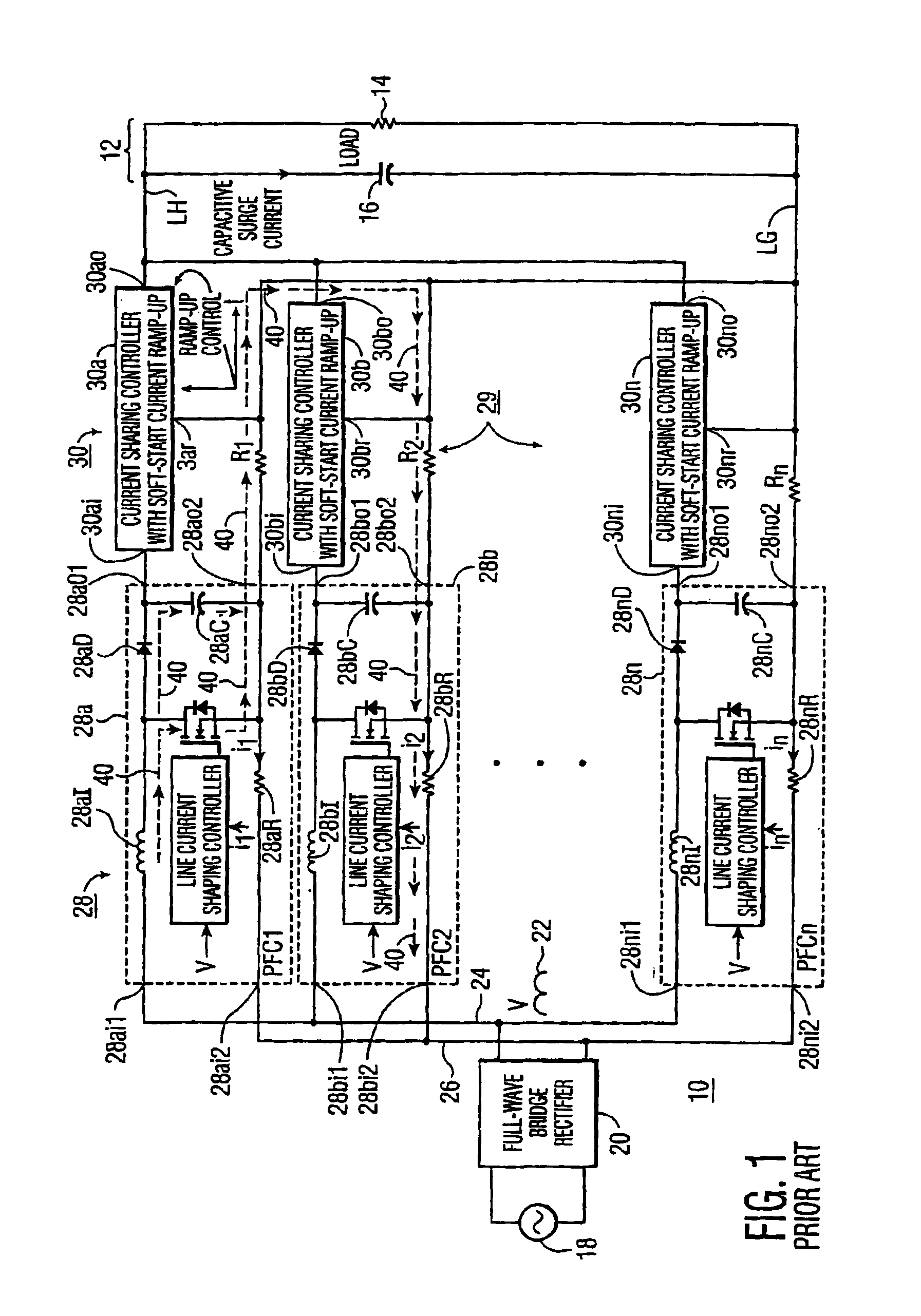
[0021]It has been discovered that the arrangement of FIG. 1 may not be as stable or consistent in performance as desired. More particularly, it has been discovered that a forward cross circulation current, represented in FIG. 1 as a dash line 40, can flow from one PFC module to another, as for example from PFC module 28a to PFC module 28b, returning to conductor 26. This cross circulation current tends to disrupt the current sensing mechanism of the affected module, and eventually the AC line current shaping. In addition, the uncontrolled circulation may easily exceed the rating of the current-balancing resistors of the PFC modules, such as resistor 28bR of module 28b, for example, and lead to component destruction. Further, the cross circulation current also causes signal ground drift (reference shift) and erroneous signal processing.

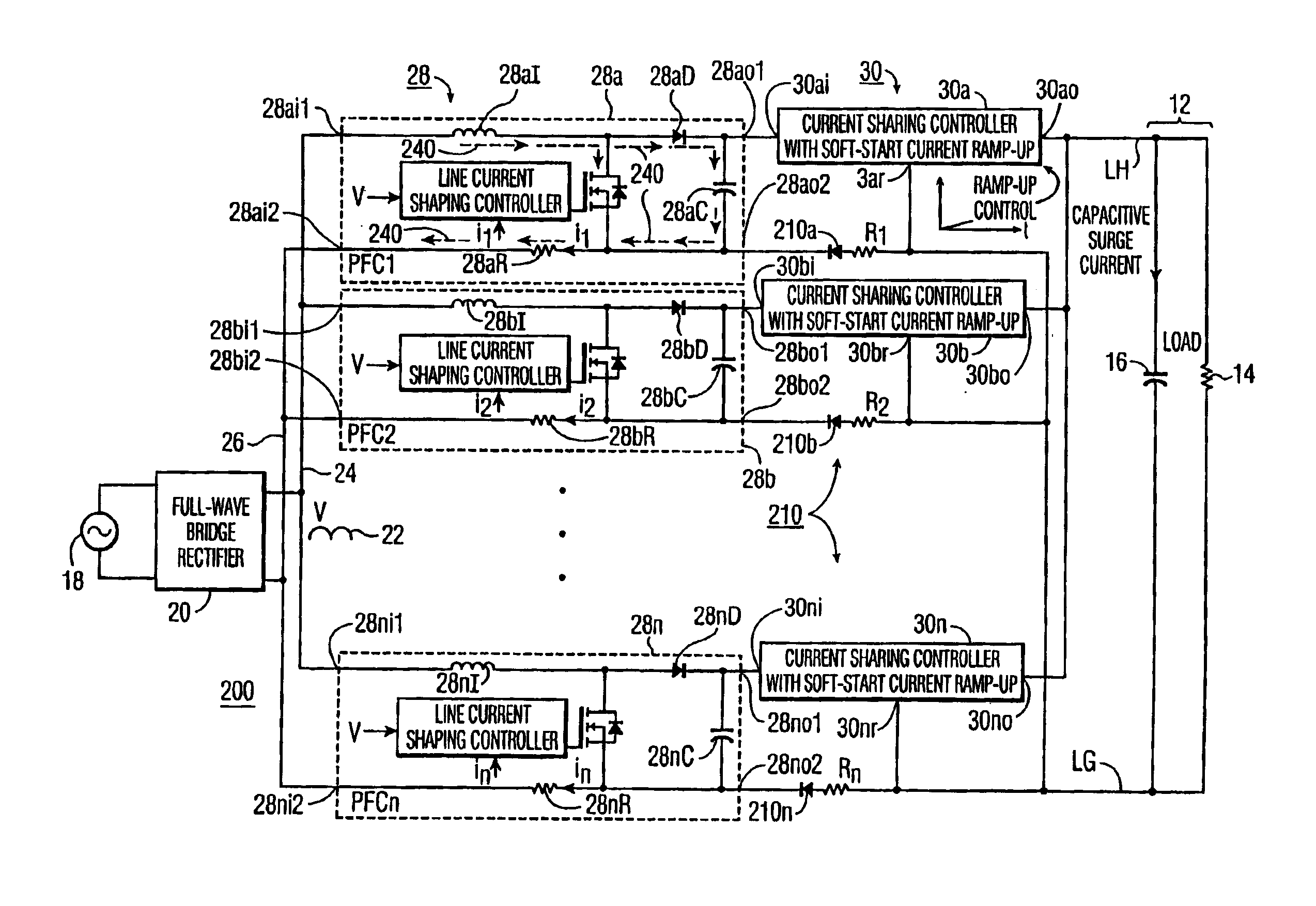
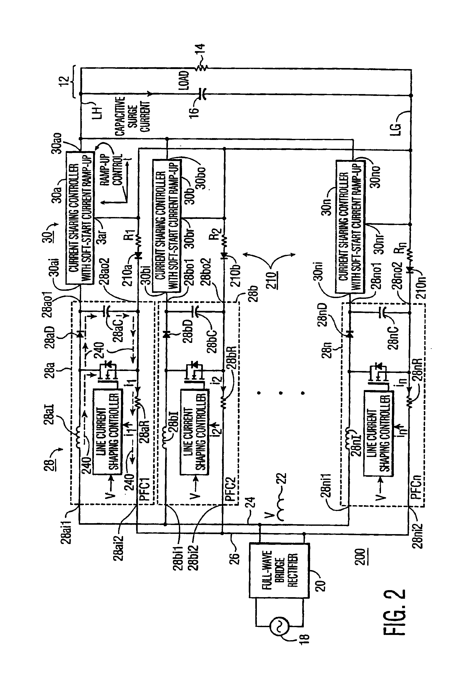
[0022]According to an aspect of the invention, the circulation of cross currents from one module to the others is prevented by the use of unidirection...


PUM


Abstract

A power supply for a capacitive-resistive load includes plural paralleled phase correcting modules together with current sharing controllers for tending to equalize their currents. Each module is provided with a diode, poled to prevent forward current from flowing in the return current path, for aiding in equalizing module currents. Surge currents are reduced by a single saturable reactor coupled to the combined outputs of current sharing controllers, thereby avoiding the need for soft-start in each controller. A precharging path extends from a source of pulsating direct voltage to the load, for precharging the load capacitance at turn-on.

Description

GOVERNMENTAL INTEREST[0001]This invention was prepared under government contract N00014-99-2-0002 (HBMRS). The United States Government has a non-exclusive, non-transferable, paid-up license in this invention.FIELD OF THE INVENTION[0002]This invention relates to electrical power supplies, and more particularly to paralleled power supplies in which, variously, turn-on surge currents are controlled, unidirectional return current equalization is assured, and a capacitive load is precharged.BACKGROUND OF THE INVENTION[0003]It is often necessary to parallel power supplies in order to achieve a desired level of power. Such paralleling allows the use of standardized or commercial-off-the-shelf (COTS) modules or units to achieve a level of power which might otherwise require a costly custom-designed power supply. For example, most single-phase power-factor-corrected (PFC) boost AC-DC power supplies available as COTS modules offer no more than 1 KW of power capacity, and must be paralleled i...

Claims


Application Information

Patent Timeline
Patent Type & Authority Patents(United States)
IPC IPC(8): H02M3/158H02M3/04H02M1/00H02M1/42
CPCH02M3/1584H02M1/4225H02M1/36Y02B70/126Y02B70/10
Inventor WU, KENG-CHIH
Owner LOCKHEED MARTIN CORP
Why Eureka
Try Eureka