Method of writing servo tracks for disk file apparatus using write start or stop sectors

a disk file and servo track technology, applied in the direction of digital signal error detection/correction, instruments, recording signal processing, etc., can solve the problems of continuous vibration, deterioration of stw quality, and deterioration of write quality of servo track, so as to improve the quality of head positioning information

Inactive Publication Date: 2005-06-07
TOSHIBA STORAGE DEVICE CORP
View PDF13 Cites 17 Cited by
  • Summary
  • Abstract
  • Description
  • Claims
  • Application Information

AI Technical Summary

Benefits of technology

[0008]Accordingly, the object of the present invention is to provide a STW method for a disk file apparatus such as magnetic disk unit, in which the servo track quality can be improved by suppressing the step, i.e. the misalignment between the write start position and the write end position of the servo track which is caused by the continuous vibration asynchronous with the spindle rotation.
[0016]With the STW method for the disk file apparatus according to the invention, the continuous vibration asynchronous with the rotational frequency of the spindle motor is detected, and the STW operation is performed based on the resulting detection signal. Therefore, a radial step or misalignment hardly occurs between the write starting position and the write ending position at the time of STW, thereby improving the quality of the head positioning information written by the STW operation.

Problems solved by technology

In the case where the moving accuracy of the push pin is low, therefore, the problem of a deteriorated write quality (STW quality) of the servo track arises.
Another probable cause of deterioration of the STW quality is the continuous vibration, asynchronous with the rotational frequency of the spindle motor, due to the bearing of the spindle motor for rotating the disk medium.

Method used


Image

  • Method of writing servo tracks for disk file apparatus using write start or stop sectors
  • Method of writing servo tracks for disk file apparatus using write start or stop sectors
  • Method of writing servo tracks for disk file apparatus using write start or stop sectors

Examples


first embodiment

[0070][First Embodiment]

[0071]The first embodiment uses an accelerometer as a means for detecting the continuous vibration asynchronous with the rotational frequency of the spindle motor. A configuration of an apparatus for realizing the method according to the first embodiment is shown in FIG. 8.

[0072]In FIG. 8, numeral 20 designates a disk file apparatus mounted on the servo track writer 30 described with reference to FIG. 6. A housing 21 has arranged therein a disk medium 2 rotated by the spindle motor 3, a carriage 5 having a head and a VCM 4 for driving the carriage 5. According to the first embodiment, an accelerometer 7 is mounted on the housing 21 of the disk file apparatus 20 or the fixing jig of the disk file apparatus 20 of the servo track writer 30. The accelerometer meter 7 can be mounted by pressing it against the housing with a spring or by attaching it with adhesive such as wax. In some cases, it is possible to use the output of the accelerometer attached on the carr...

second embodiment

[0082][Second Embodiment]

[0083]The second embodiment uses a displacement gauge as a means for detecting the continuous vibration out of phase with the rotational frequency of the spindle motor. The only difference in the second embodiment from the first embodiment is to use a displacement gauge in place of the accelerometer. Thus, the system configuration for realizing the second embodiment is different only in that the accelerometer 7 has been replaced by the displacement gauge 8. FIGS. 10A, 10B show two types of the displacement gauge 8 and the mounting position used in the second embodiment.

[0084]According to the second embodiment, the displacement gauge 8 is used as a means for detecting the asynchronous continuous vibration fc, which is detected from the output of the displacement gauge 8 as measured on the rotary portion (hub or the like) of the disk medium 2 or the spindle motor 3. The displacement gauge 8 is installed, as shown in FIG. 10A, at two positions (measuring points...

third embodiment

[0090][Third Embodiment]

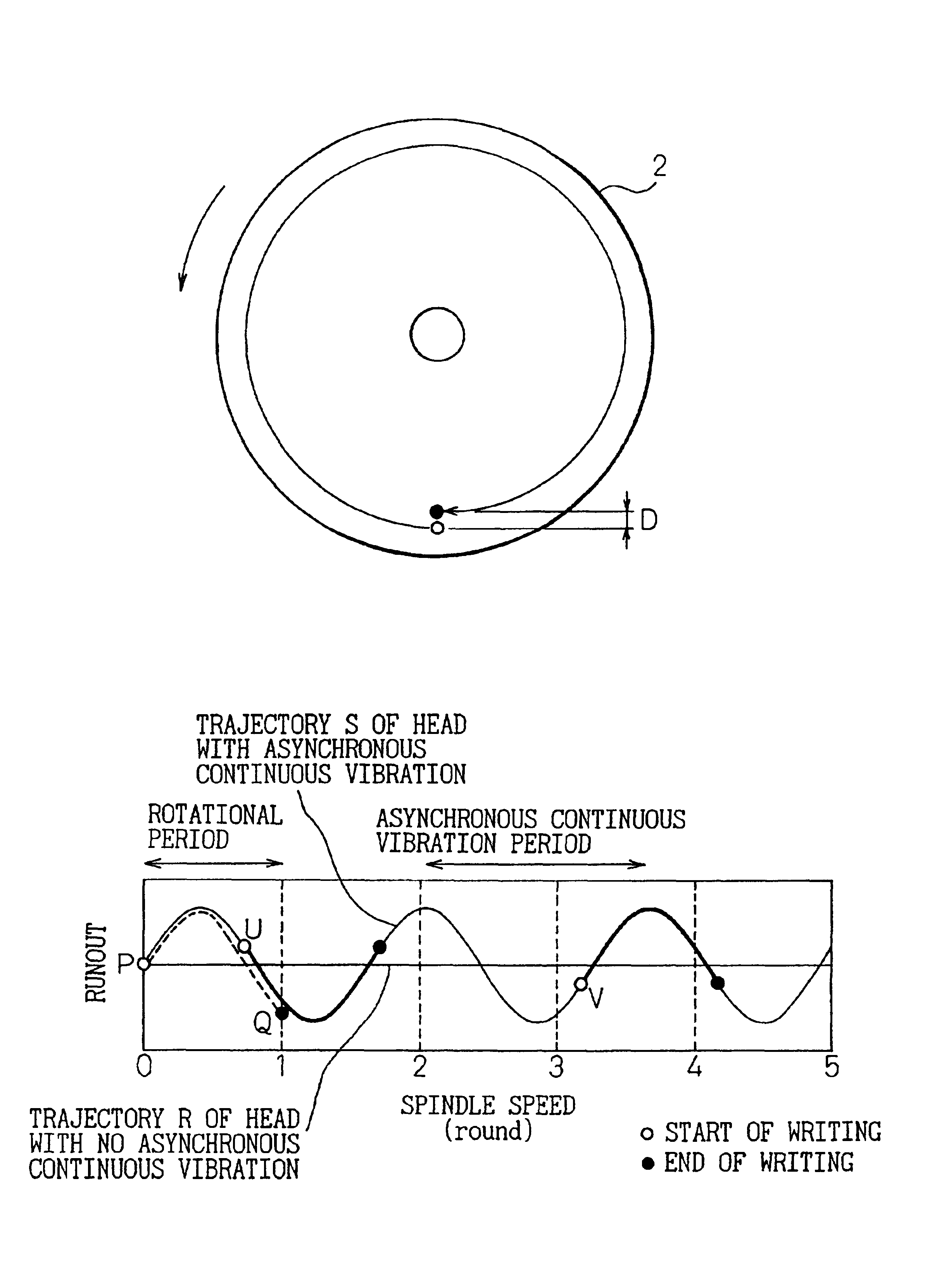
[0091]The first embodiment uses an accelerometer and the second embodiment uses a displacement gauge as a means for detecting the continuous vibration asynchronous with the rotational frequency of the spindle motor. According to the third embodiment, on the other hand, the head itself in the disk file apparatus is used for detecting the asynchronous continuous vibration. The STW signal is read with the same head that has effected STW, and the asynchronous continuous vibration is detected from the signal thus read. In the case where the rotational accuracy of the spindle motor is so high that the asynchronous continuous vibration occurs steadily, the constant observation of the asynchronous continuous vibration is not required, but the phase is checked once every several tracks in which the data are written, as in the first and second embodiments.

[0092]In a STW method, the head positioning signal is written in the first several tracks of the data zone in accor...


PUM

PropertyMeasurementUnit
frequencyaaaaaaaaaa
rotational frequency fraaaaaaaaaa

Abstract

A method of STW (servo track write) for improving the quality of the servo tracks by suppressing the misalignment of the write start position caused by the asynchronous continuous vibration of a disk drive is disclosed. The disk drive includes a spindle motor, a disk medium, a write / read head and a head moving mechanism for carrying out the sector servo operation. The STW method comprises the steps of detecting the continuous vibration asynchronous with the rotational frequency of the spindle motor, detecting the phase of the asynchronous continuous vibration detected, determining the write start sector of each servo track based on the detected phase of the asynchronous continuous vibration, determining the write start time of each servo track in accordance with the clock signal, and moving the head onto the servo track where the head positioning information is written, by the head moving mechanism and writing the information in the servo track based on the write start time.

Description

BACKGROUND OF THE INVENTION[0001]1. Field of the Invention[0002]The present invention relates to a method of writing servo tracks for a disk file apparatus or, in particular, to a method of writing servo tracks for a disk file apparatus such as a magnetic disk unit used as an external recording apparatus for computers, in which the quality of the servo tracks formed on the disk medium can be improved.[0003]2. Description of the Related Art[0004]In recent years, disk file apparatuses such as a magnetic disk unit and an optical disk unit have been used as an external storage unit for computers. In such a disk file apparatus, the storage capacity of the disk medium is increasing year by year. In the case where the size of the disk medium is fixed, therefore, the increased storage capacity makes it necessary to increase the TPI (tracks per inch) by narrowing the pitch of the recording tracks on the disk medium.[0005]In a disk file apparatus such as a magnetic disk unit, on the other han...

Claims


Application Information

Patent Timeline
Patent Type & Authority Patents(United States)
IPC IPC(8): G11B19/20G11B21/10G11B5/596
CPCG11B5/59633
Inventor KUROBA, YASUMASAYAMADA, TOMOYOSHI
Owner TOSHIBA STORAGE DEVICE CORP
Why Eureka
Try Eureka