System and method for measuring polarization dependent gain of an optical amplifier

a technology of optical amplifiers and polarization dependent gain, which is applied in the direction of electromagnetic transmission, transmission monitoring, instruments, etc., can solve the problem of reducing the effect of polarization dependent loss, and achieve the effect of effective measuring the polarization dependent gain of an optical amplifier

Inactive Publication Date: 2005-06-07
AGILENT TECH INC
View PDF6 Cites 2 Cited by
  • Summary
  • Abstract
  • Description
  • Claims
  • Application Information

AI Technical Summary

Benefits of technology

[0012]Embodiments of the present invention, to be discussed in detail below, represent a system and method that effectively measures the polarization dependent gain of an optical amplifier without significantly introducing error into that measurement. As has been done in the past, a saturating optical signal source generates an optical signal capable of saturating the optical amplifier. That optical signal is then randomly polarized by a slow polarization scrambler, resulting in a polarized optical signal that is used as an input signal for the optical amplifier under test. Unlike previous test systems, however, the output signal of the optical amplifier is then transferred to a fast polarization scrambler, resulting in a PDG measurement signal, which is then presented to an optical signal analyzer that measures that signal's intensity level for each channel of the signal.

Problems solved by technology

Typically, use of the fast polarization scrambler greatly reduces the effect of the polarization dependent loss normally associated with such a test system on the polarization gain measurement of the optical amplifier.

Method used


Image

  • System and method for measuring polarization dependent gain of an optical amplifier
  • System and method for measuring polarization dependent gain of an optical amplifier
  • System and method for measuring polarization dependent gain of an optical amplifier

Examples


Embodiment Construction

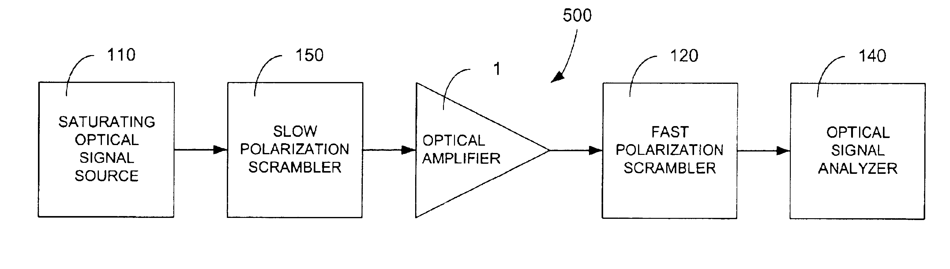
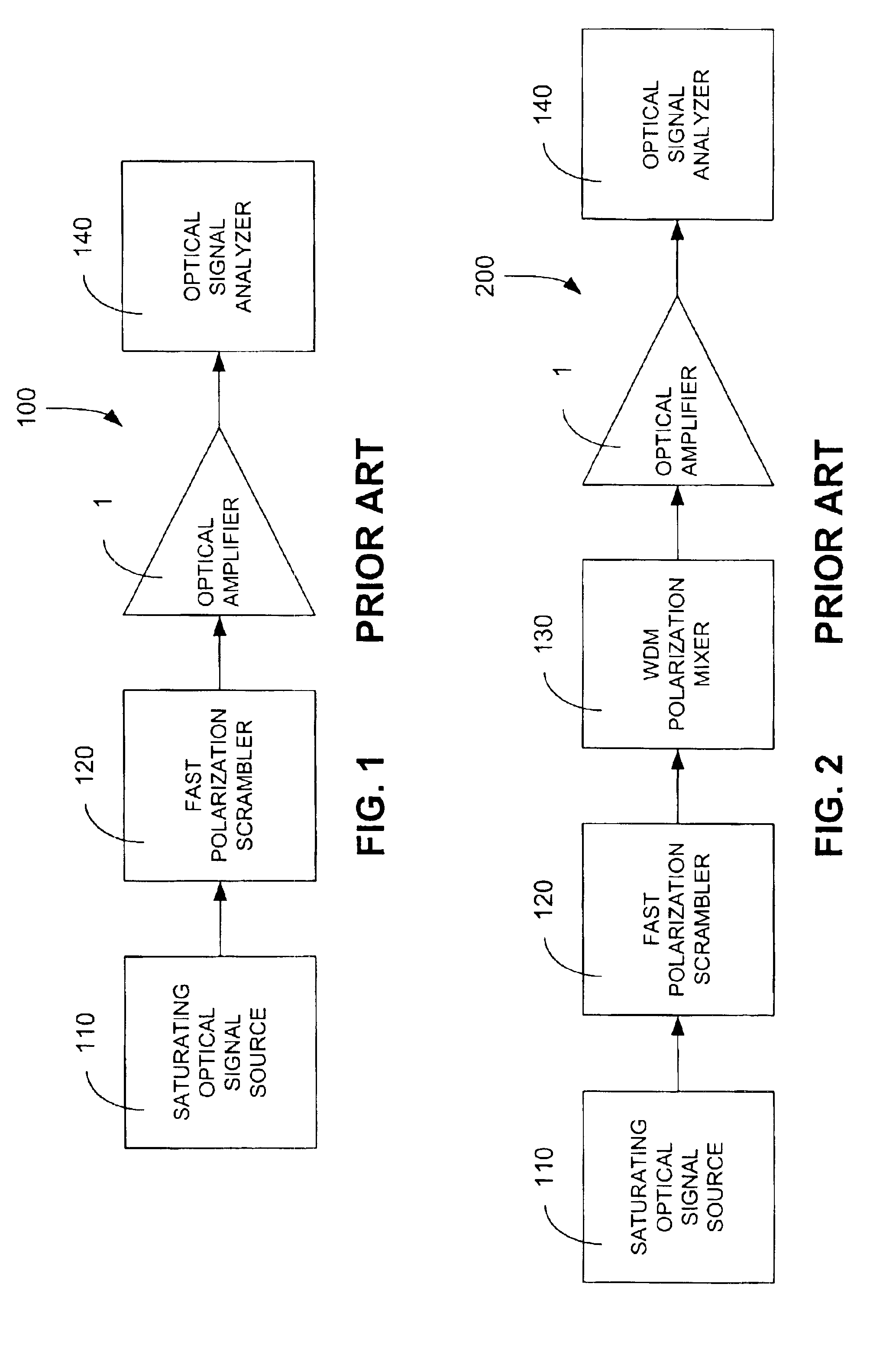
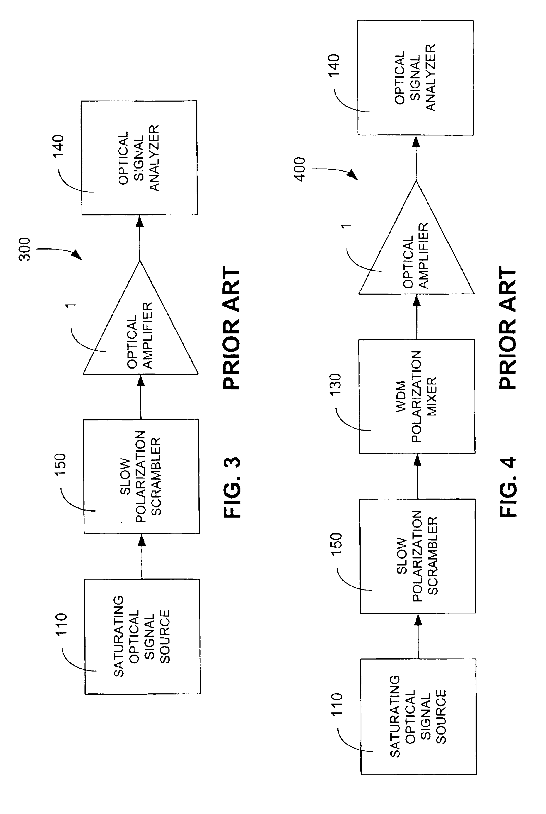
[0023]Embodiments of the invention, a first and second improved optical amplifier test systems 500 and 600, are shown in FIG. 5 and FIG. 6. These improved test systems 500, 600 utilize essentially the same components as the third and fourth optical amplifier test systems 300, 400 of FIG. 3 and FIG. 4, but with at least one major enhancement, to be discussed below. First, a saturating signal source 110 generates an optical signal that will saturate the optical amplifier 1. Saturation, whereby the intensity level of the input signal is high enough so that small changes in the input signal of the optical amplifier 1 result in essentially no change in the intensity level of the output signal, is the normal operating condition of the optical amplifier. Dependent upon whether single-channel or multiple-channel tests are desired, the saturating signal source 110 may be either a single channel or WDM source.

[0024]As previously discussed in FIG. 3 and FIG. 4, a slow polarization scrambler 15...


PUM


Abstract

A system and method that effectively measures the polarization dependent gain of an optical amplifier without significantly introducing error into that measurement is provided. A saturating optical signal source generates an optical signal capable of saturating the optical amplifier. A slow polarization scrambler then randomly polarizes the optical signal to yield a polarized optical signal, which is used as an input signal of the optical amplifier. The output signal of the optical amplifier is then transferred to a fast polarization scrambler, resulting in a PDG measurement signal, which is then presented to an optical signal analyzer that measures the intensity level of each channel of the PDG measurement signal. Alternately, a wavelength division multiplexing (WDM) polarization mixer is employed to mix the polarization states of WDM channels of the polarized optical signal from the slow polarization scrambler with respect to each other, yielding the input signal for the optical amplifier under test.

Description

BACKGROUND OF THE INVENTION[0001]Optical fiber networks are playing an increasingly important role in high-speed communications networks. To handle the increasing data rates and bandwidths expected of these networks, advances in optical communication technology continue to be made at a brisk pace. One of the vital components of optical fiber networks that continues to be improved upon is the optical amplifier, which is charged with the task of initially transmitting, or later boosting, an optical signal along an optical fiber. Such optical signals may be characterized as either single-channel or multiple-channel signals. Multiple-channel signals are normally implemented via wavelength division multiplexing (WDM), whereby the wavelength spectrum of the optical signal is apportioned into multiple wavelength segments, each of which implements a separate communications channel, thereby increasing overall communications bandwidth. As optical amplifiers for these optical networks become m...

Claims


Application Information

Patent Timeline
Patent Type & Authority Patents(United States)
IPC IPC(8): H04B10/08H01S3/00
CPCH04B10/0731
Inventor BEAL, DAVID A.MILLER, PATRICIA S
Owner AGILENT TECH INC
Why Eureka
Try Eureka