Incremental lithography mask layout design and verification

a lithography mask and layout technology, applied in the field of lithography processing, can solve the problems of increasing the size of the mask, reducing the time to produce the mask layout, and reducing so as to reduce the time for manual viewing, reduce the concern for operating system instability, and reduce the effect of mask layou

Inactive Publication Date: 2005-06-07
SYNOPSYS INC
View PDF5 Cites 36 Cited by
  • Summary
  • Abstract
  • Description
  • Claims
  • Application Information

AI Technical Summary

Benefits of technology

[0009]Methods and apparatuses for incrementally designing and verifying a lithography mask layout are described. By designing and verifying a mask layout incrementally, that is by first processing a layout defining a target pattern to produce a mask layout and verifying the entire mask layout over an initial iteration and then p

Problems solved by technology

Because the amount of data defining a mask layout rapidly grows in size as the mask layout is processed, the time to process and verify a mask layout over multiple iterations is relatively long.
The time to open a f

Method used


Image

  • Incremental lithography mask layout design and verification
  • Incremental lithography mask layout design and verification
  • Incremental lithography mask layout design and verification

Examples


example use

of Mask Layout

[0073]A lithography mask layout that has been designed and verified incrementally from an input layout defining a target pattern may be used for any suitable purpose to print the target pattern.

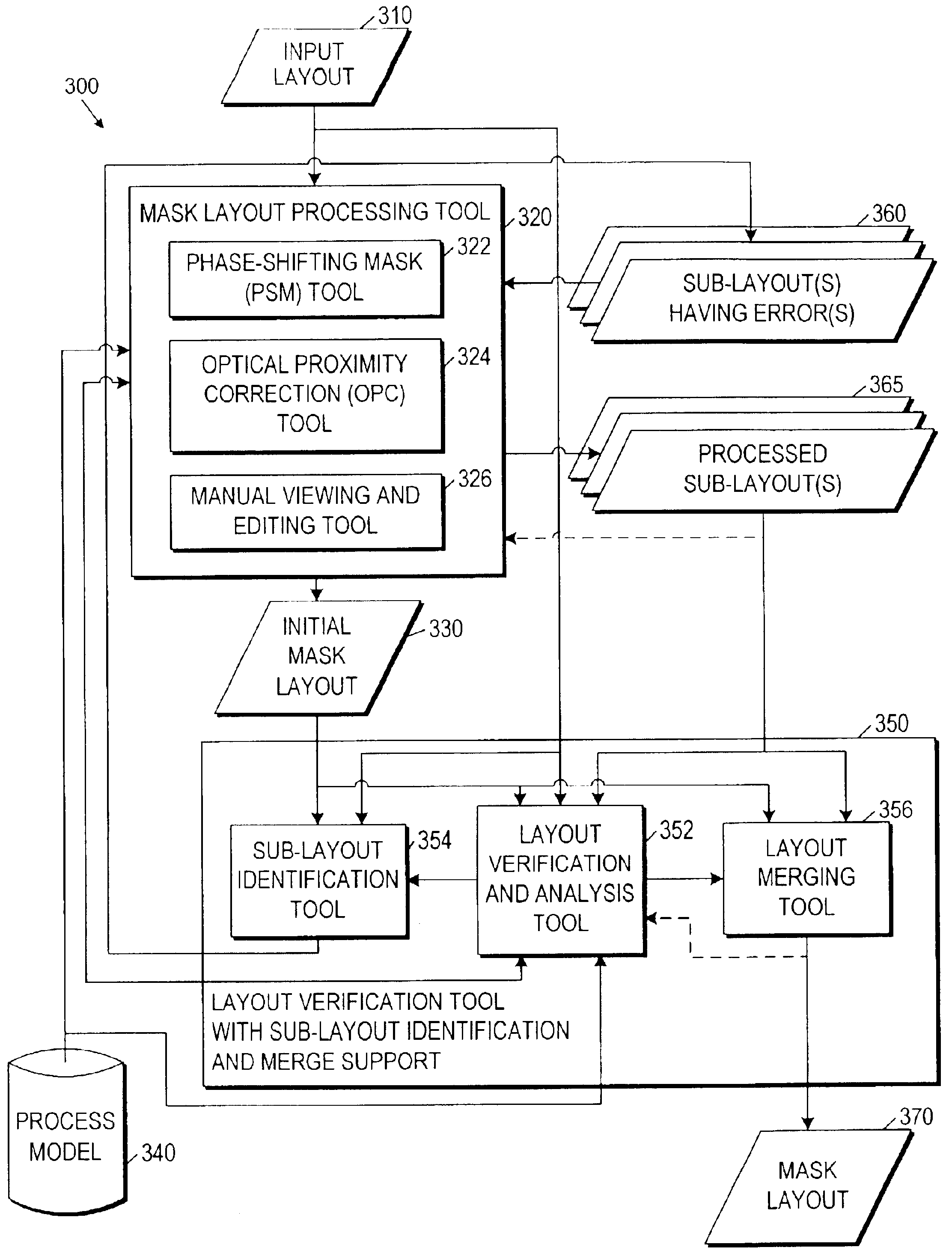
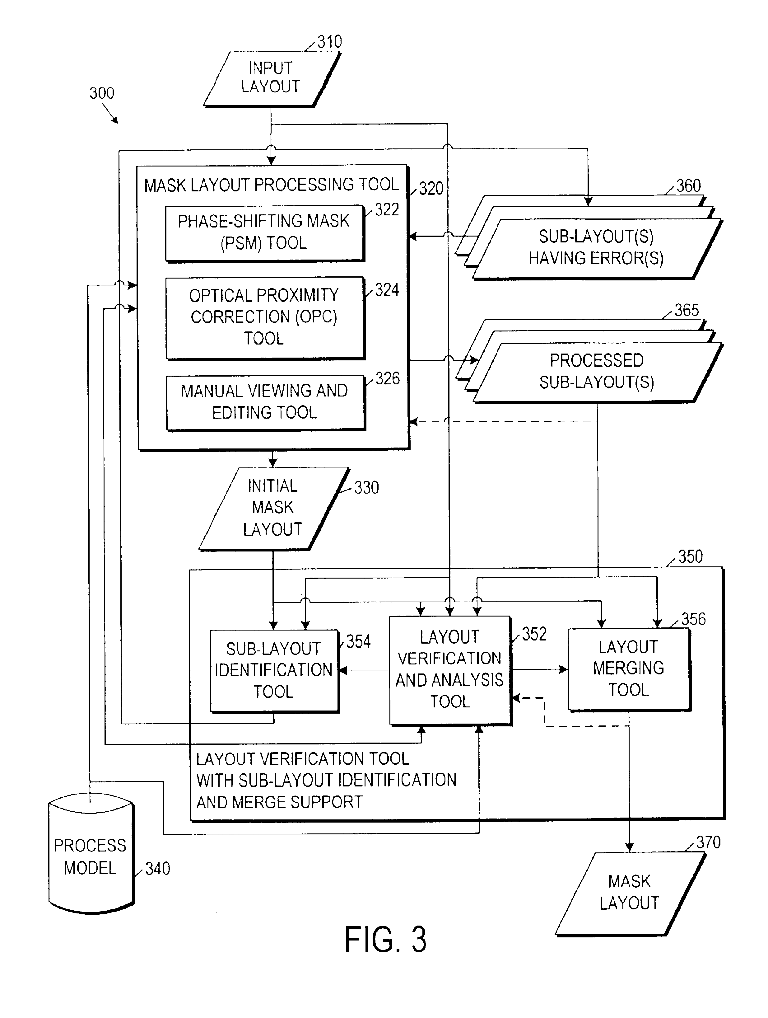
[0074]FIG. 6 illustrates, for one embodiment, a system 600 to help manufacture an integrated circuit (IC) 685 using a mask layout 655 that has been incrementally designed and verified. As illustrated in FIG. 6, system 600 comprises a process model generator 610, a process model calibrator 620, an integrated circuit layout generator 630, a mask layout processing tool 640, a layout verification tool 650 with sub-layout identification and merge support, a mask data preparation (MDP) tool 660, mask manufacturing equipment 670, and lithography equipment 680.

[0075]Process model generator 610 generates a preliminary process model based on a predetermined set of lithography process parameters 602 to be used to print a target pattern in manufacturing IC 685. Process model calibrator 620 ...


PUM


Abstract

A lithography mask layout is designed and verified incrementally to help reduce the amount of time to produce the mask layout. For one embodiment, a layout defining a target pattern may be processed to produce a mask layout, and the mask layout may be verified to identify errors. Rather than processing and verifying the entire mask layout for error correction over one or more subsequent iterations, sub-layouts having errors may be removed or copied from the mask layout for separate processing and verification. Because the amount of data defining a sub-layout is relatively small, the time to design and verify the mask layout is reduced. The resulting mask layout having one or more processed and verified sub-layout(s) may then be used to manufacture a mask set to help print the target pattern in manufacturing integrated circuits (ICs), for example.

Description

BACKGROUND[0001]1. Field of the Invention[0002]The present invention relates generally to the field of lithography processing. More particularly, the present invention relates to the field of lithography mask layout design and verification.[0003]2. Description of Related Art[0004]The layout of a lithography mask set for use in manufacturing integrated circuits (ICs), for example, may be designed by processing a layout defining a target pattern to be printed using the mask set to help compensate for lithography distortions and / or to help reduce the size of features. Designing a mask layout in this manner may therefore help increase IC yield and / or help increase performance and reduce power consumption.[0005]The layout defining the target pattern may be processed, for example, to introduce phase-shifting mask (PSM) regions in the mask layout to help define features with dimensions less than the wavelength of the radiation to be directed through the mask set in printing the mask layout...

Claims


Application Information

Patent Timeline
IPC IPC(8): G06F9/45G06F17/50G03F1/36
CPCG06F17/5081G03F1/36G03F1/68G06F30/398
Inventor TSAI, CHI-MINGLIN, CHIN-HSENWANG, YAO-TING
Owner SYNOPSYS INC
Why Eureka
Try Eureka