
Fuel filling device and fuel leakage detection method

Inactive Publication Date: 2005-06-14
NITTO KOHKI CO LTD +1
View PDF7 Cites 24 Cited by
  • Summary
  • Abstract
  • Description
  • Claims
  • Application Information

AI Technical Summary

Benefits of technology

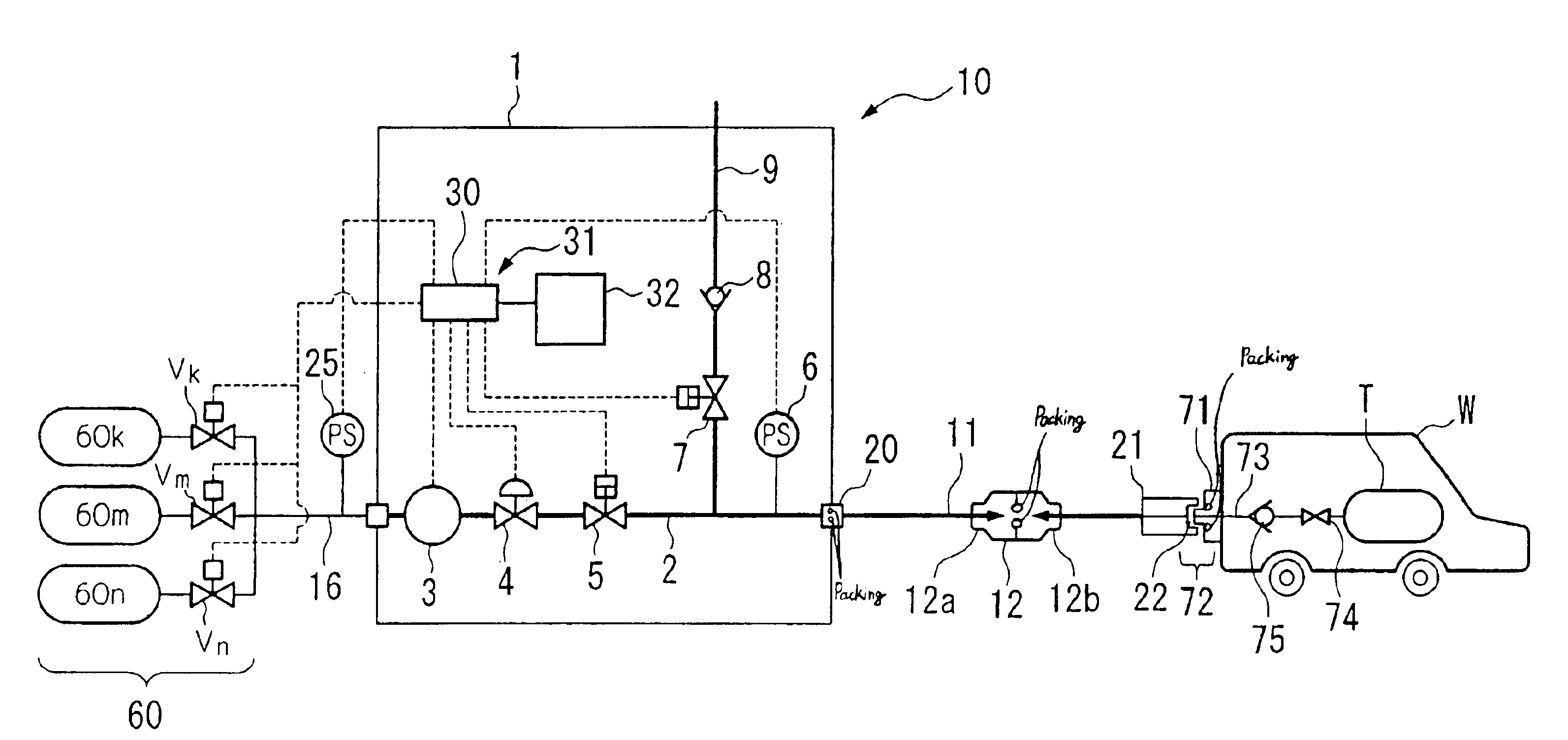
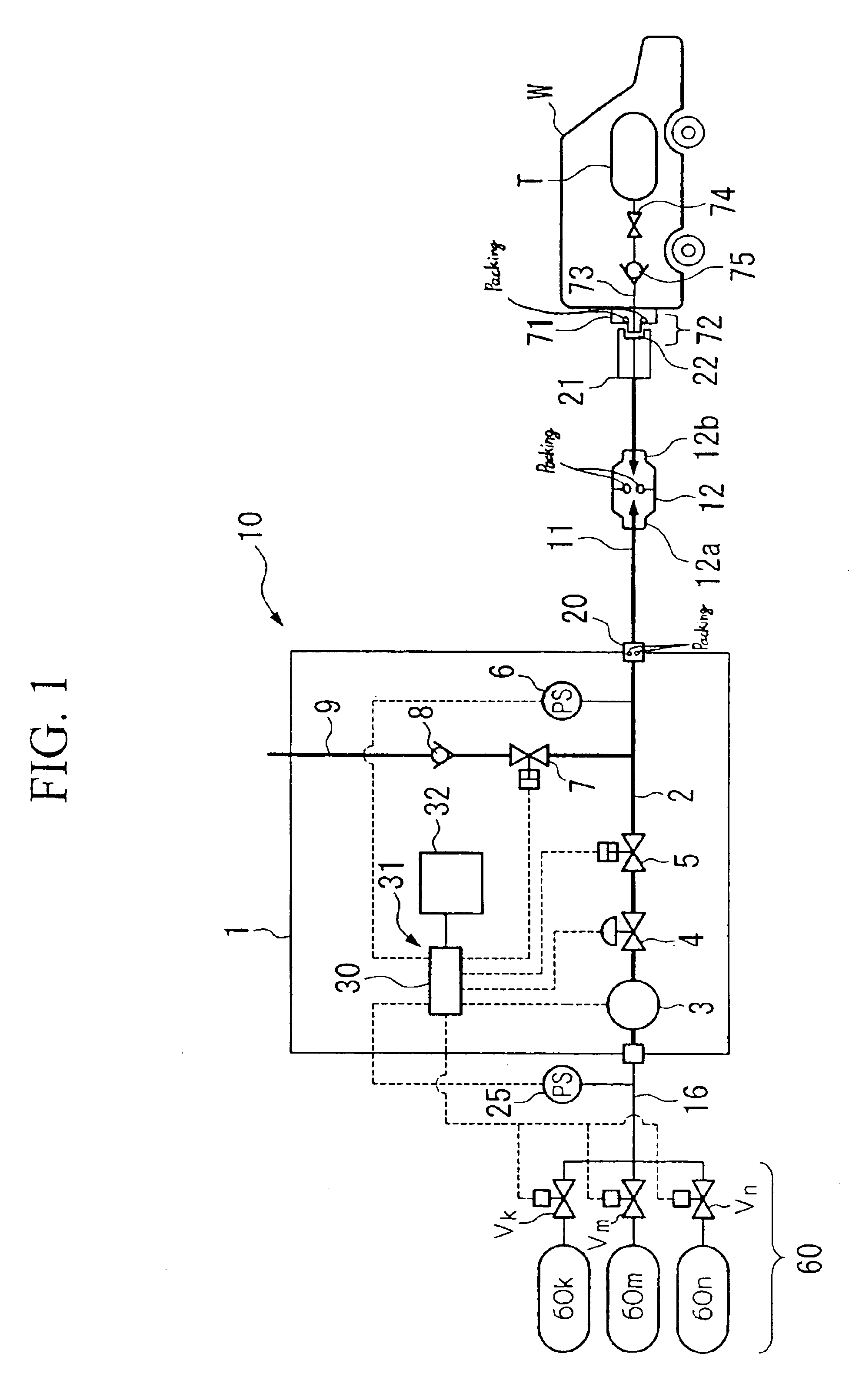
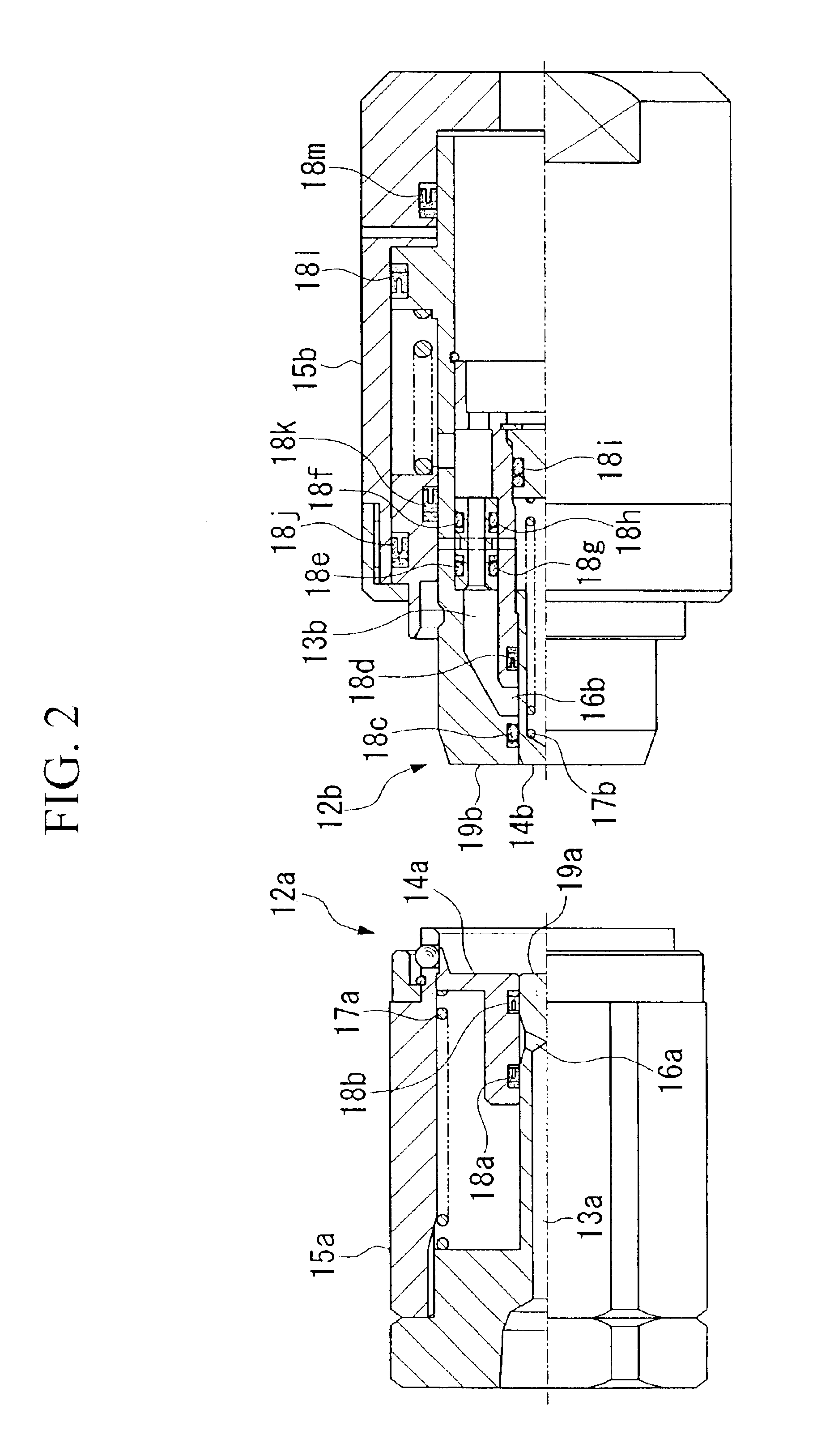
[0055]Consequently, the packings used in each of the composite equipment that compose the fuel filling device can be prevented from being exposed to high-pressure fuel for a long period of time while in the standby state, and permeation of fuel into the packings can be prevented in advance.
[0056]Accordingly, deterioration of packings caused by permeation of fuel can be prevented, and fuel leakage and other accidents can be prevented.
[0057]In addition, since pressure inside a nozzle is at low pressure in the standby state, operations such as connection and release of the nozzle can be facilitated.

Problems solved by technology

Consequently, it is not desirable to allow these gases to be retained within hoses and other lines.
If fuel is allowed to be retained in the lines at this high pressure, fuel may permeate into the packings used in component machinery due to penetration, and this permeated fuel may cause deterioration of the packings as a result of swelling inside the packings when pressure drops at the start of filling.
Since hydrogen gas in particularly is highly penetrable with respect to the packings due to its small molecules, allowing hydrogen to be retained in the lines was undesirable.
In addition, in the case fuel is allowed to be retained in the lines in a high pressure state, since the inside of nozzle 65 reaches a high pressure, the pressing force of the packing against the surface inside nozzle 65 that contacts the packing becomes higher, resulting in the problem of it being difficult to open and close the valve of nozzle 65, while also making it difficult to attach and release nozzle 65 to and from automobile W.

Method used


Image

  • Fuel filling device and fuel leakage detection method
  • Fuel filling device and fuel leakage detection method
  • Fuel filling device and fuel leakage detection method

Examples


examples

[0137]A packing durability test was conducted in the manner described below. The specimens used in this testing are indicated below.

(1) Rubber Materials

[0138](a) Materials: acrylonitrile butadiene rubber, hydrogenated acrylonitrile butadiene rubber, ethylene propylene rubber, fluorine rubber, chlorinated butyl[0139](b) Shape: dumbbell (JIS K 6251 No. 3) and O-ring (AS568A-116)

(2) Resin Materials[0140](a) Materials: polyoxymethylene (polyacetal), nylon (polyamide), polyphenylenesulfide[0141](b) Shape: dumbbell (Type ASTM1, thickness: 3 mm)

(3) Resin (Coated) Materials[0142](a) Materials: main body; silicone resin, fluororesin, coating; Teflon (registered trademark)[0143](b) Shape: O-ring (AS568A-116)

[0144]The test method is described below.

[0145]After placing the specimen in a container, filling the container with hydrogen gas, and allowing to stand for 1 week at a pressure of 35 MPa, the hydrogen gas was evacuated from the container. When evacuating the hydrogen gas, evacuation was c...


PUM

PropertyMeasurementUnit
Fractionaaaaaaaaaa
Fractionaaaaaaaaaa
Fractionaaaaaaaaaa

Abstract

A fuel filling device is provided with a fuel supply adjusting section which adjusts the amount of fuel supplied, a fuel feed line which feeds fuel from a fuel supply adjusting section to a vehicle W, a nozzle removably coupled to vehicle W that supplies fuel from fuel feed line to vehicle W, and a discharge device that discharges fuel present within fuel feed line to the outside to prevent deterioration of packings used in the device in the case of filling a fuel at high pressure, while also facilitate the operation of a filling nozzle.

Description

BACKGROUND OF THE INVENTION[0001]1. Field of the Invention[0002]The present invention relates to a fuel filling device that fills hydrogen or compressed natural gas as fuel into a vehicle, and to a method of detecting fuel leakage of a fuel filling device.[0003]2. Description of Related Art[0004]Development is proceeding on hydrogen automobiles and compressed natural gas automobiles using hydrogen gas and compressed natural gas for fuel as next-generation automobiles. These automobiles are characterized by low emission levels of carbon dioxide gas, NOx, SOx, and other pollutants.[0005]When refueling these automobiles, the automobiles are driven to a refueling station provided with a fuel filling device (dispenser) that fills the hydrogen gas or compressed natural gas used as fuel, and fuel is then replenished at that refueling station in the same manner as current gasoline-fueled automobiles.[0006]Studies are being conducted on the safety and other aspects of these automobiles and f...

Claims


Application Information

Patent Timeline
IPC IPC(8): F17C5/00B67D7/04F17C5/06F17C13/00F17C13/12
CPCF17C5/00F17C2270/0168F17C2205/0142F17C2205/0326F17C2205/0335F17C2205/037F17C2221/012F17C2221/033F17C2227/04F17C2227/043F17C2250/0426F17C2250/0439F17C2250/0443F17C2250/0636F17C2260/038F17C2265/065Y02E60/321Y02E60/32B67D7/54
Inventor SATOU, KAZUTOSHITAKANO, NAOYUKISHIRANE, YOSHIKAZUGOTOU, KUNIHIKOMATSUMOTO, KOJI
Owner NITTO KOHKI CO LTD
Learn More