Cementing manifold assembly

a cementing manifold and assembly technology, applied in the direction of fluid removal, sealing/packing, borehole/well accessories, etc., can solve the problems of reducing the overall pressure-containing capacity of the cementing manifold, and affecting the operation of the well

Inactive Publication Date: 2005-06-14
SMITH INT INC
View PDF17 Cites 83 Cited by
  • Summary
  • Abstract
  • Description
  • Claims
  • Application Information

AI Technical Summary

Benefits of technology

[0023]In one aspect, the preferred embodiments of the present invention feature a cementing manifold providing a number of advantages over conventional cementing manifolds. In particular, the preferred embodiments of the cementing manifolds of the present invention preferably include: modular housings that can be stacked together and interconnected to add multi-dart or multi-sphere capability; identical, interchangeable valves; internal bypass capability; a minimum number and minimum size of penetrations into the pressure containing

Problems solved by technology

A number of disadvantages are associated with cementing manifolds having external connections, such as external bypass lines and side-mounted sphere dropping mechanisms.
These penetrations create high stress concentration areas and hydraulically loaded areas that reduce the overall pressure-containing capacity of the cementing manifold.
Further, the ball drop mechanism and external bypass connections protrude a considerable distance from the main body of the manifold, making these components more prone to damage during well operations.
In addition, the external components connect via threads or welds to the main body of the manifold, thereby presenting a safety concern.
In particular, the threads could back out or the welds could fail, which would expose rig personnel to high pressure, high velocity fluids.
Thus, many of the concerns associated with external bypass manifolds have not been eliminated.
Further, the parallel flow bores restrict the flow capacity of the TDH unit, which could present erosion problems, and also

Method used


Image

  • Cementing manifold assembly
  • Cementing manifold assembly
  • Cementing manifold assembly

Examples


Embodiment Construction

[0039]Preferred embodiments of the invention are shown in the above-identified Figures and described in detail below. In describing the preferred embodiments, like or identical reference numerals are used to identify common or similar elements.

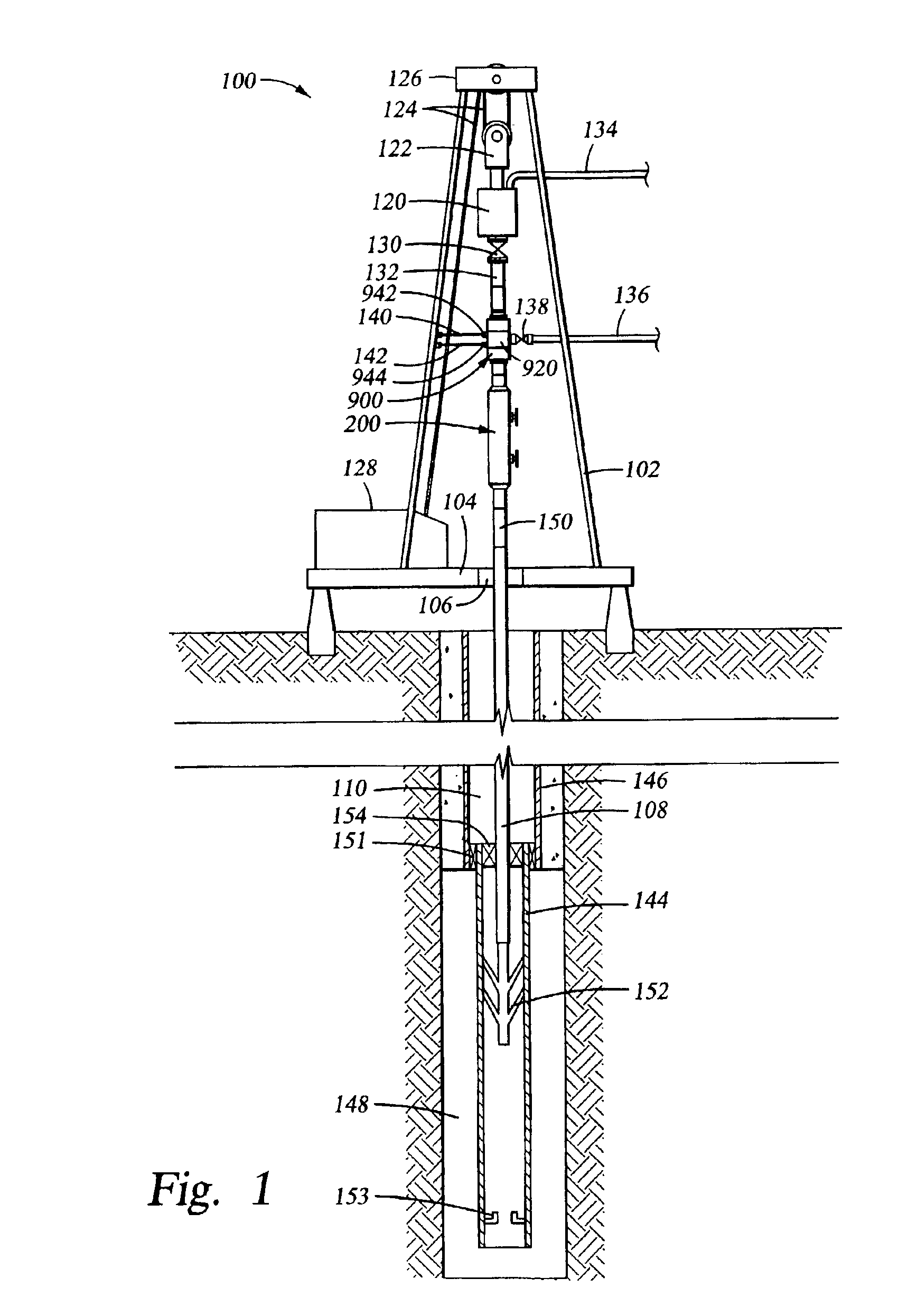
[0040]FIG. 1 schematically depicts an exemplary drilling system in which the present invention may be utilized. However, one of ordinary skill in the art will understand that the preferred embodiments are not limited to use with a particular type of drilling system. The drilling rig 100 includes a derrick 102 with a rig floor 104 at its lower end having an opening 106 through which drill string 108 extends downwardly into a well bore 110. The drill string 108 is driven rotatably by a top drive drilling unit 120 that is suspended from the derrick 102 by a traveling block 122. The traveling block 122 is supported and moveable upwardly and downwardly by a cabling 124 connected at its upper end to a crown block 126 and actuated by conventional pow...


PUM


Abstract

A cementing manifold is disclosed that preferably includes: modular housings that can be stacked together and interconnected to add multi-dart or multi-sphere capability; identical, interchangeable valves; internal bypass capability; a minimum number of protrusions into the pressure containing components; and no externally mounted welded or threaded components.
A cementing swivel is also disclosed that preferably includes connections that are formed integrally to the housing, redundant cement connections, angled cement ports, and seal assemblies that do not require individual placement of each seal.

Description

CROSS-REFERENCE TO RELATED APPLICATIONS[0001]The present application claims the benefit under 35 U.S.C. Section 111(b) of provisional application Ser. No. 60 / 310,293 filed Aug. 3, 2001, and entitled “Cementing Manifold”.STATEMENT REGARDING FEDERALLY SPONSORED RESEARCH OR DEVELOPMENT[0002]Not Applicable.BACKGROUND OF THE INVENTION[0003]1. Field of the Invention[0004]The present invention relates generally to apparatus and methods for cementing downhole tubulars into a well bore, and more particularly, the present invention relates to a cementing manifold assembly and method of use.[0005]2. Description of the Related Art[0006]A well-known method of drilling hydrocarbon wells involves disposing a drill bit at the end of a drill string and rotating the drill string from the surface utilizing either a top drive unit or a rotary table set in the drilling rig floor. As drilling continues, progressively smaller diameter tubulars comprising casing and / or liner strings may be installed end-to...

Claims


Application Information

Patent Timeline
IPC IPC(8): E21B33/03E21B33/05E21B33/13E21B33/16
CPCE21B33/16E21B33/05E21B33/165
Inventor SIMSON, JAMES A.
Owner SMITH INT INC
Why Eureka
Try Eureka