
Protective case for use with a belt

Inactive Publication Date: 2005-06-14
CHEE BILL TSANG CHUN
View PDF16 Cites 26 Cited by
  • Summary
  • Abstract
  • Description
  • Claims
  • Application Information

AI Technical Summary

Benefits of technology

[0007]For the reasons cited above, it is an object of the present invention to provide a protective case with a fastening means that enables removable attachment of the case to a belt clip. It is a further object to provide such a protective case with such a fastening means that avoids nuisance protrusions on the protective case. It is a yet further object to provide such a protective case with such a fastening means that is quickly and easily attached or detached from the case.
[0008]The objects of the invention are achieved by providing a protective case with a fastening means embedded in the case in such a way that the case may easily be attached to a belt clip. The case has a shell comprising hinged front and rear panels. When closed, the shell encloses and securely holds a handheld device. The shell is constructed of rigid material, such as a metal or a form-rigid material that protects the handheld device from damage if dropped. Such form-rigid material also includes leather or other materials that have sufficient stiffness and body to form the bubble and properly hold the nut in place.
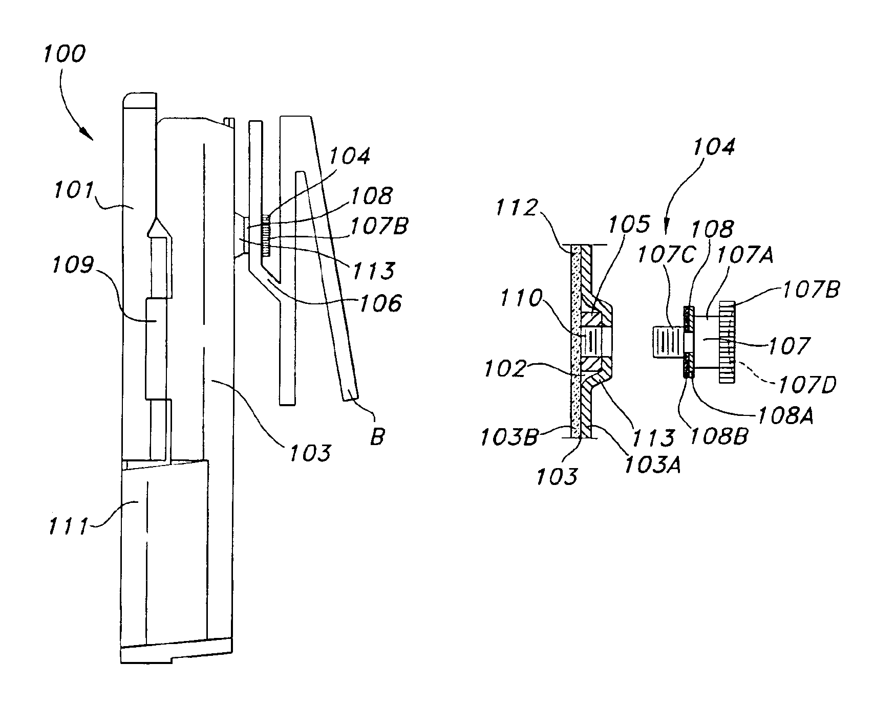
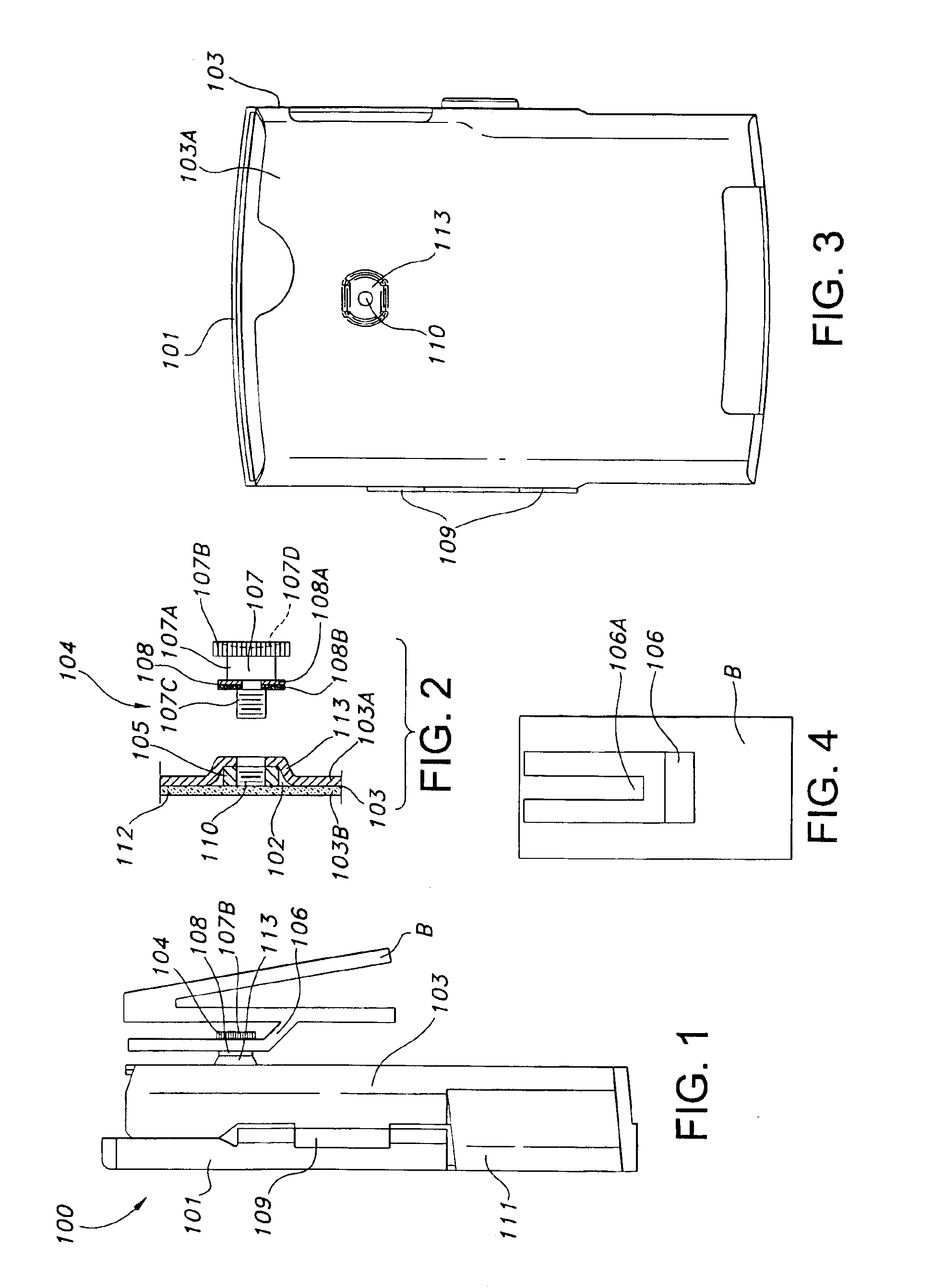
[0009]The fastening means used in the protective case comprises a female-male threaded fastener. The female connector is a nut that is enclosed in a bubble on the rear panel and. The male connector is a post that has three sections: a threaded shaft, a support shaft, and a head. The threaded shaft threads into the nut and the support shaft, now extending from the rear panel, is slidingly insertable into a groove on a belt dip, such that the head is captured behind the groove. It is a key feature of the protective case according to the invention that the post is easily removable from the protective case by simply unscrewing it. Thus, if the user opts not to use a belt clip, the post does not present a nuisance protrusion that is a source of injury, or that can catch on clothing, and scratch or mar surfaces.
[0012]The inner surface of the shell is covered with a backing and this backing, in addition to protecting the encased handheld device from being scratched or damaged, also serves as a practical means for retaining the nut in the recess. Ideally, the backing is of a material that provides an aesthetic covering that is pleasant to the touch and also provides some shock absorption, should the encased handheld device be dropped. Examples of appropriate backing materials include non-woven fabrics, natural or synthetic fabrics, such as rubber, neoprene, suede leather, etc. It should be understood that many types of material are suitable for the backing, including metal, a rigid backing plate, or composite constructions of materials. The primary requirement of the backing material is that it be strong enough to prevent the nut from falling out of the recess or shifting away from the shell toward the inner area of the case, so that it becomes difficult or impossible to thread the post into the nut.
[0013]The protective case according to the invention is suitable for use with many different types of handheld devices such as PDAs, MP3 players and cell phones, i.e., any handheld device. To prepare the protective case for attachment to a belt clip, the threaded shaft is inserted into the recess and threaded into the nut. The post now protrudes from the case. The head of the post is easily and quickly captured in the belt clip by sliding the body into the groove. To remove the case from the belt clip, the post is simply slid out of the groove. To use the protective case without the belt clip, the post is easily removed from the case leaving only the smooth bubble on the outer surface of the rear panel.

Problems solved by technology

This has the disadvantage in that it is inconvenient to remove the protective case without removing the belt.
This allows the user to remove the protective case easily from the belt, but is disadvantageous in that the case is cumbersome when it is not on the belt, because of the appended belt clip.
Fixedly attaching the post to the device or the case has the disadvantage in that the post cannot be disengaged from the case or device, thus leaving a protrusion on the case or device that may be a nuisance.

Method used


Image

  • Protective case for use with a belt
  • Protective case for use with a belt

Examples


Embodiment Construction

[0019]FIGS. 1 and 2 illustrate a protective case 100 according to the invention. FIG. 1 shows the protective case 100 suspended from a belt clip B. The protective case 100 comprises a shell 101 and a removable fastening means 104. The shell 101 includes a rear panel 103, a front panel 111 and a hinge 109. The rear panel 103 has an outer surface 103A and an inner surface 103B. The fastening means 104 comprises a female connector 105, a male connector 107 and a washer 105. The female connector is hereinafter referred to as a “nut” and the male connector as a “post.” The post 104 includes a threaded shaft 107C, a support shaft 107A and head 107B. A concave area or recess 102, with a convex area or corresponding bubble 113, is formed in the rear panel 103. The bubble 113 is a smooth, raised contour on the outer surface 103A. A through-bore 110 is provided through the center of the bubble 113, as shown in FIG. 2. The shell 101 is preferably constructed of a rigid material such a metal or...


PUM


Abstract

A protective case that may be used with or without a belt clip. A recess is formed in the inside surface of rear panel of the case, with a corresponding slight, smooth bubble formed on the outside surface of the rear panel. The bubble of the recess has a through-bore. A nut is embedded into the recess and held in place by a backing affixed to the inside surface of the rear panel. A threaded post with a head may be threaded into the the nut in the recess. The case is then easily captured in the belt clip by sliding the post into a groove on the clip. If the user desires to use the protective case without the belt clip, the post is easily removed from the rear panel, leaving only the slightly raised, smooth bubble.

Description

BACKGROUND INFORMATION[0001]1. Field of the Invention[0002]The invention relates to the field of protective cases for handheld devices. More particularly, the invention relates to a protective case with a belt clip fastening system.[0003]2. Description of the Prior Art[0004]The user of a handheld device often carries the handheld device in a protective case. Typically, the protective case is constructed of a sturdy, rigid material that protects the handheld device from damage. Ideally, the user carries the device in a manner that makes it readily available for immediate use. This often means carrying the device attached to or close to the user's body. A common method of carrying the device within easy reach is to clip the protective case to the user's belt. There are numerous known ways of attaching the protective case to the user's belt. One such method is to provide a loop on the back of the case, through which the belt is then fed. This has the disadvantage in that it is inconven...

Claims


Application Information

Patent Timeline
IPC IPC(8): A45F5/00
CPCA45F5/00A45F5/021A45C2011/002A45F5/02Y10S224/93A45F2005/026A45F2200/0516
Inventor CHEE, BILL TSANG CHUN
Owner CHEE BILL TSANG CHUN
Learn More