Sheet finisher and image forming system using the same

a technology of image forming system and sheet stack, which is applied in the direction of electrographic process, paper/cardboard containers, instruments, etc., can solve the problems of reducing productivity, reducing the pressing time available with a single fold roller pair, and insufficient transfer of the pressing force of the roller pair to the sheet stack

Inactive Publication Date: 2005-06-14
RICOH KK
View PDF23 Cites 136 Cited by
  • Summary
  • Abstract
  • Description
  • Claims
  • Application Information

AI Technical Summary

Benefits of technology

[0024]It is an object of the present invention to provide a sheet finisher capable of neatly

Problems solved by technology

A problem with the above configuration, causing a fold roller pair to fold a sheet stack, is that the pressing force of the roller pair cannot be sufficiently transferred to a sheet stack because the entire width of a sheet stack passes the nip of the roller pair in an extremely short period of time.
However, a pressing time available with a single fold roller pair is limited because the nip width of the roller pair is extremely small.
Further, the above proposal reduces productivity.
In any case, however, a period of time over which a sheet stack is pressed by the nip of a fold roller pair is short because the axis of each fold roller extends perpendicularly to a direction of sheet conveyance.
However, the reinforce roller scheme taught in the above document has the following problems (1) through (7) when the sheet stack is thick.
At this instant, the reinforce roller is apt to produce noise due to an impact.
(4) When a belt, which transfers a driving force to the reinforce roller, twists due to the tilt of the reinforce roller, it is likely that the durability of the belt is reduced or the belt slips out.
(8) When the number of sheets stapled together is small, the interval between consecutive sheet stacks is short, making

Method used


Image

  • Sheet finisher and image forming system using the same
  • Sheet finisher and image forming system using the same
  • Sheet finisher and image forming system using the same

Examples


first embodiment

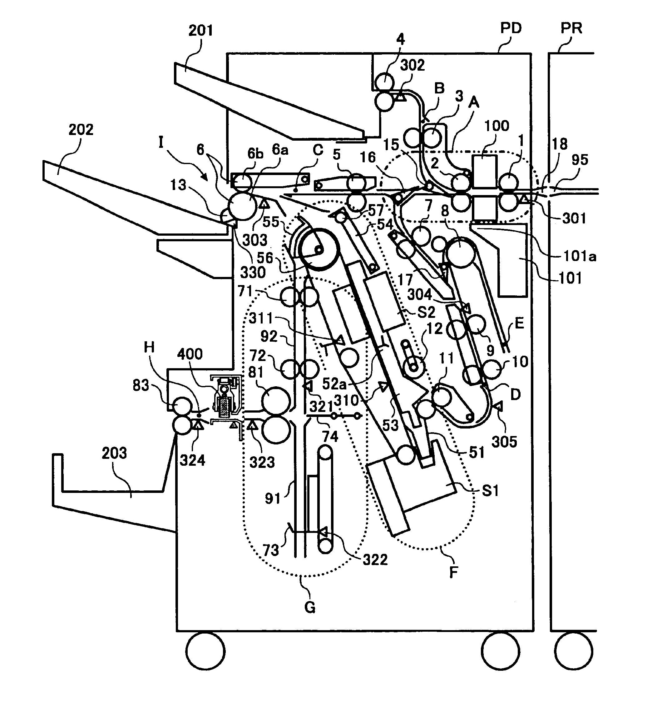
[0145]Referring to FIG. 1 of the drawings, an image forming system embodying the present invention is shown and directed mainly toward the first object. As shown, the image forming system is generally made up of an image forming apparatus PR and a sheet finisher PD operatively connected to one side of the image forming apparatus PR. A sheet or recording medium driven out of the image forming apparatus PR via an outlet 95 is introduced in the sheet finisher PD via an inlet 18. In the sheet finisher PD, a path A extends from the inlet 18 and includes finishing means for finishing a single sheet. In the illustrative embodiment, this finishing means is implemented as a punch unit or punching means 100. Path selectors 15 and 16 steer the sheet coming in through the path A to any one of a path B terminating at an upper tray 201, a path C terminating at a shift tray 202, and a processing tray F. The processing tray F is used to position, staple or otherwise process a sheet or sheets and, i...

second embodiment

[0238]Reference will be made to FIGS. 64 and 65 for describing a second embodiment of the present invention Briefly, in the center staple and bind mode or fold reinforcement mode, the illustrative embodiment causes the reinforce roller 409 to press the fold of a sheet stack during each of forward and backward movements. A step S513 at which a procedure shown in FIG. 64 starts follows the step S512 of FIG. 32. Because the procedure of FIG. 65 is identical with the procedure described with reference to FIGS. 32 through 34 except for the steps S526 through S519, the following description will concentrate on differences between the two procedures.

[0239]As shown in FIG. 64, after a sheet stack has been conveyed to the pressing position assigned to the reinforce roller 409 in the step S526, whether or not the position sensor 412 responsive to the home position of the reinforce roller 409 has turned on is determined (step S551). If the answer of the step S551 is YES, then the pulse motor 4...

third embodiment

[0244]A third embodiment of the present invention will be described with reference to FIGS. 66 through 72. In the first embodiment, the flange 419 is formed of an elastic material while the elastic material 421 is provided on the lower guide member 416, thereby reducing noise ascribable to the step between the sheet stack and the lower guide plate 416. The third embodiment is configured to control the moving speed of the reinforce roller 409 for the same purpose as the first embodiment.

[0245]A distance from the home position (abbreviated as HP hereinafter) of the reinforce roller 409 to one edge of a sheet stack, i.e., a press start position and a distance from the other edge of the sheet stack, i.e., a press end position to the stop position of the roller 409 can be calculated on the basis of sheet size information received from the image forming apparatus PR. Every sheet stack is dislocated in the direction perpendicular to the direction of conveyance before arriving at the reinfo...


PUM

PropertyMeasurementUnit
Timeaaaaaaaaaa
Forceaaaaaaaaaa
Sizeaaaaaaaaaa

Abstract

A sheet finisher of the present invention is included in an image forming system and folds a stack of sheets sequentially transferred from an image forming apparatus thereto. The sheet finisher includes a fold roller pair for holding the stack of sheets being conveyed via a nip thereof. A reinforce roller reinforces the fold of the folded sheet stack in cooperation with a guide plate. A drive mechanism causes the reinforce roller to move in a direction perpendicular to a direction of sheet conveyance. A shock absorbing member is located at a position where the reinforce roller and guide plate contact each other.

Description

BACKGROUND OF THE INVENTION[0001]1. Field of the Invention[0002]The present invention relates to a sheet finisher mounted on or operatively connected to a copier, printer or similar image forming apparatus for folding, sorting, stacking, stapling, center-stapling and binding, folding or otherwise finishing a sheet or a sheet stack, and an image forming system consisting of the sheet finisher and image forming apparatus.[0003]2. Description of the Background Art[0004]A sheet finisher positioned at the downstream side of an image forming apparatus for stapling or otherwise finishing a sheet stack is well known in the art. To meet the increasing demand for multiple functions, a sheet finisher having a center-stapling capability in addition to the conventional edge-stapling capability has recently been proposed. Further, a sheet finisher with a center-folding capability in addition to the center-stapling capability has been proposed to fold a center-stapled sheet stack at the center for...

Claims


Application Information

Patent Timeline
IPC IPC(8): B65H45/12B65H45/18G03G15/00
CPCB65H45/18G03G15/65B65H2301/4227B65H2301/4505G03G2215/00877B65H2301/51232B65H2701/13212B65H2301/4532B65H2701/1829
Inventor YAMADA, KENJINAGASAKO, SHUUYATAMURA, MASAHIROSUZUKI, NOBUYOSHISAITOH, HIROMOTOOKADA, HIROKIIIDA, JUNICHIANDOH, AKIHITOANDOH, RIKAKIKKAWA, NAOHIROTOKITA, JUNICHI
Owner RICOH KK
Why Eureka
Try Eureka