Composite cross member system

a cross-member system and composite technology, applied in the field of composite cross-member systems, can solve the problems of affecting the service life of the frame, and the design of the member does not allow convenient serviceability, so as to improve the service life, increase the rigidity of the frame system, and the frame is extra rigid.

Inactive Publication Date: 2005-06-14
VOLVO TRUCKS NORTH AMERICA
View PDF19 Cites 10 Cited by
  • Summary
  • Abstract
  • Description
  • Claims
  • Application Information

AI Technical Summary

Benefits of technology

[0010]In yet another embodiment of the invention, a plurality of composite cross-members are positioned orthoganally to the two frame rails to form a frame system for an over-the-highway or off-highway truck or tractor. A stiffening member may be attached to both frame rails over the span of two adjacent composite cross-members to provide extra stiffness in the frame when increased frame system rigidity is needed.
[0011]The new design has many advantages over the current design. The new design allows for better serviceability. Service shops can easily remove the cross-member. The new cross-member design can be removed by simply removing the cross-member from the mounting brackets and replacing a new cross-member. Easy removal of the new cross-member saves time and money when service is required.
[0012]With the disclosed design, a truck or tractor frame can contain common cross-members. For example, from the second bend in the frame back, excluding the over the transmission cross-member and the rear closing cross-member can be the same. The face sheets of the new design contain flat surfaces on both sides of the cross-member for easier mounting of components such as brake lines, electrical wires and the like. The new cross-member will allow for dramatic weight reduction in the vehicle which in turn leads to lower operating cost of the vehicle. The lighter cross-member can improve a manufacturer's assembly efficiency.

Problems solved by technology

Frame roll usually results from the load put on the frame by fuel tanks, battery boxes and other components attached to the frame rail.
Such a design includes cross-members that are bulky and heavy.
Many cross-member designs do not allow for convenient serviceability.
This process is very time consuming and expensive.

Method used


Image

  • Composite cross member system
  • Composite cross member system
  • Composite cross member system

Examples


Embodiment Construction

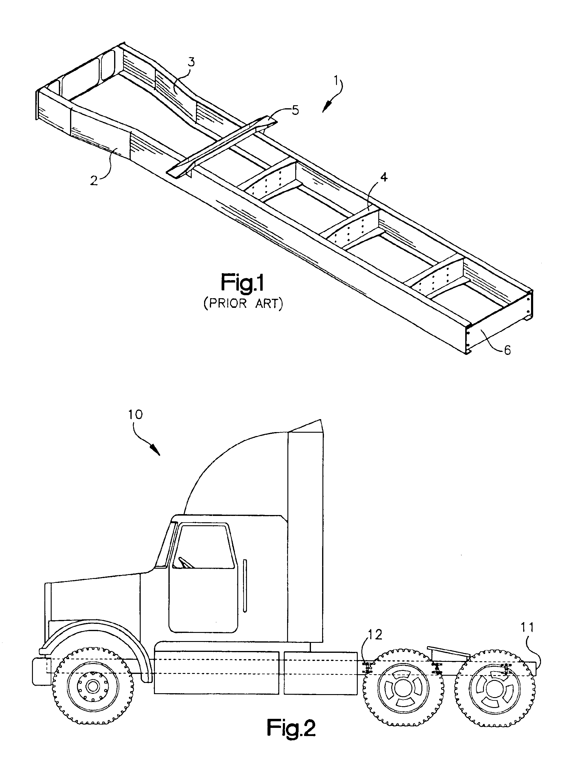
[0022]Referring now to the drawings, FIG. 2 shows an over-the-highway tractor 10 including a frame 11. The frame 11 includes composite cross-member sections 12 in accordance with the present invention.

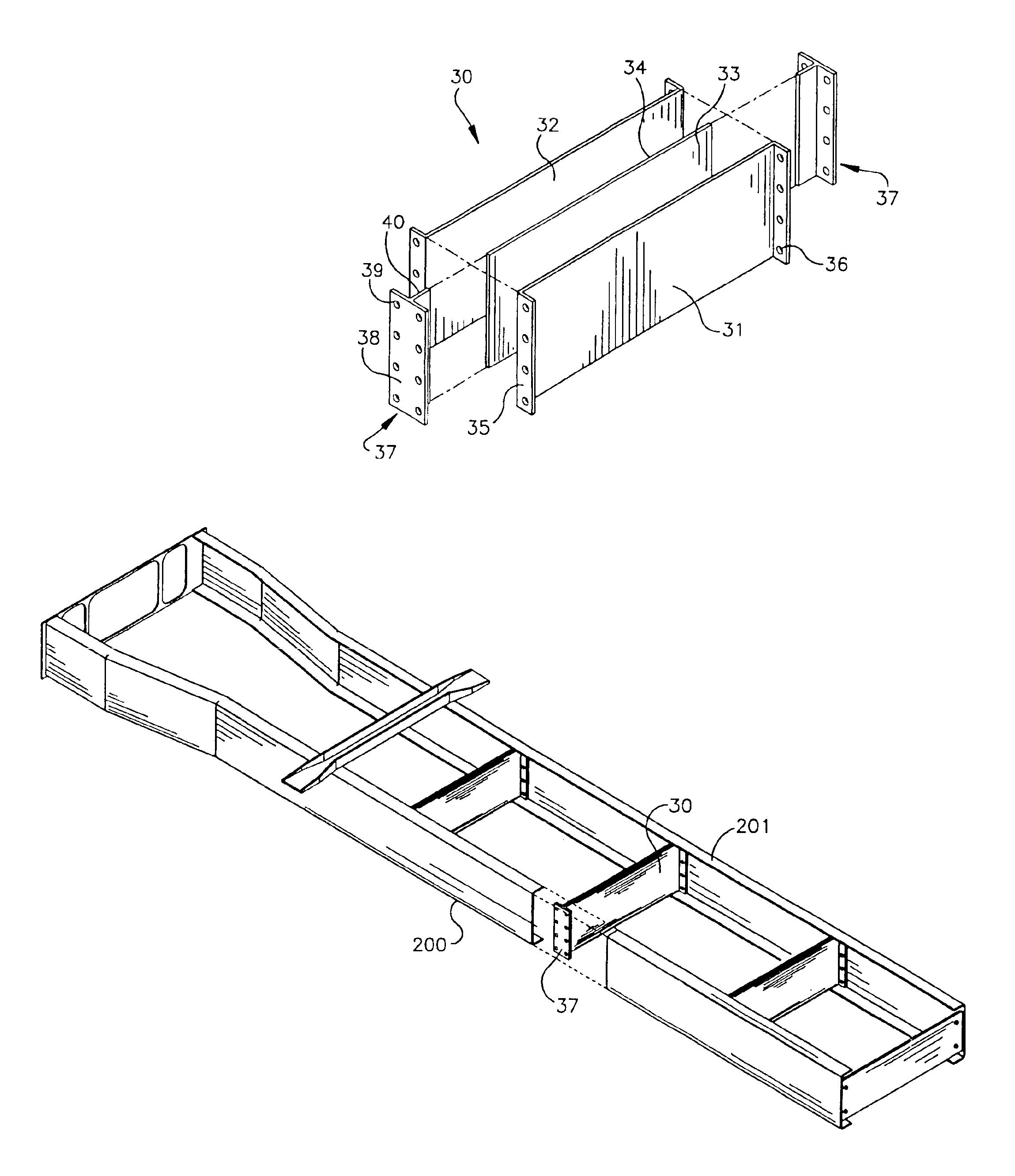
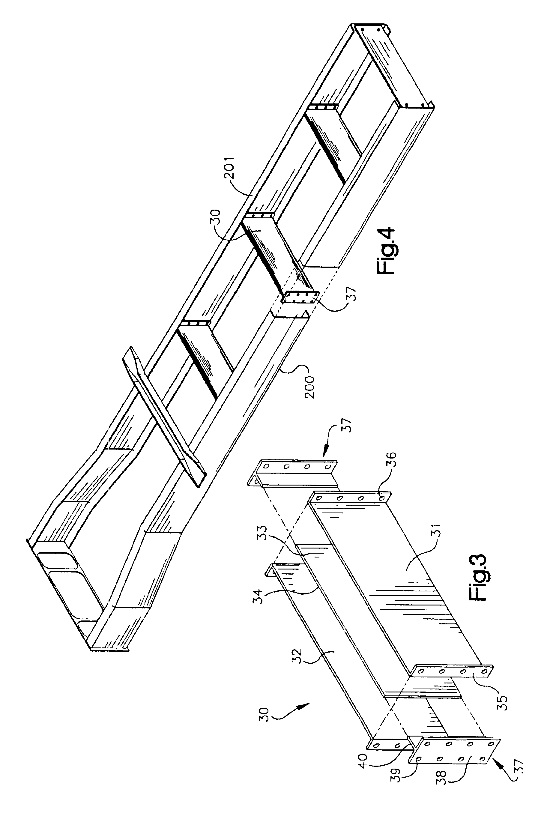
[0023]Referring to FIG. 3 the composite cross-member 30 includes a first face sheet 31 and a second face sheet 32. The face sheets 31 and 32 can be constructed from any of steel, aluminum, composite, plastic or any other suitable material as known to those of skill in the art. A core material 33 is positioned between the first face sheet 31 and the second face sheet 32. The core material 33 can be constructed from wood, plastic, honeycomb material, aluminum honeycomb, foam, nomex, plastic, any combination of these materials or any other suitable material as known to those of skill in the art. In a preferred embodiment, the core material 33 is bonded to the first face sheet 31 and second face sheet 32 by an adhesive or any other means as known to those skilled in the art. The outer edge...


PUM


Abstract

In a frame for an over the highway or off-highway truck or tractor, the frame includes a first and second frame rail and a composite cross-member comprising a first sheet, a second sheet and a core material sheet positioned between the first and second face sheet. The first and second face sheets being made of metal and plastic and the core material being made of any one of wood, plastic, honey-comb, foam and nomex. The first sheet, second sheet and core material sheet are all bonded together to form a cross-member. The cross-member is then mounted to frame rails to construct a truck or tractor frame.

Description

FIELD OF THE INVENTION[0001]The present invention relates to a composite cross-members and, more specifically, to a composite cross-members included in a chasis of an over-the-highway or off-highway truck or tractor.BACKGROUND[0002]Today, the majority of truck and tractor chassis are built around two beams that run the entire length of the vehicle. These beams are traditionally called frame rails. The frame rails are connected to each other by secondary beam structures commonly referred to as cross-members. The primary purpose of these cross-members is to form a rigid structure with the frame rail where forces and loads can be transferred from one frame rail to another so that the frame components work together as a system. A secondary function of the cross-members is to provide a surface for mounting other vehicle components such as pneumatic and electrical lines, pneumatic valves, air tanks, drive shaft supports, axle suspension equipment, engine components and towing devices.[000...

Claims


Application Information

Patent Timeline
Patent Type & Authority Patents(United States)
IPC IPC(8): B62D29/00B62D29/04B62D21/02
CPCB62D29/041B62D21/02
Inventor FOWLER, ARTHUR N.MOODIE, JOHN R.BECK, WAYNE
Owner VOLVO TRUCKS NORTH AMERICA
Why Eureka
Try Eureka