Gear shaping machine and method for the operation of a gear shaping machine

a gear shaping machine and gear technology, applied in the direction of gearing, gear-teeth manufacturing apparatus, hoisting equipment, etc., can solve the problems of affecting the operation of the whole drive train, unable to achieve certain helix angles, and all helical guides

Inactive Publication Date: 2005-06-14
LIEBHERR VERZAHNTECHNIK GMBH
View PDF15 Cites 14 Cited by
  • Summary
  • Abstract
  • Description
  • Claims
  • Application Information

AI Technical Summary

Benefits of technology

[0010]Accordingly, the stroke drive can consist of a motor-driven cam gear and a transmission linkage, which transmits the eccentric motion of the cam gear to the thrust spindle. Such stroke drives are in principle already known and are characterised by particularly robust behaviour, which is advantageous particularly in the case of the high stroke rates that are required for gear shaping machines. Stroke rates of more than 2000 strokes per minute are commonly used in the production and machining of gear wheels. The cam gear can be connected to a motor via a gear unit. The first measuring device can be designed as an angle measuring system for detecting the angle of rotation of the cam gear. In this way, the desired stroke position of the thrust spindle can thus be precisely inputted into the control of the gear shaping machine. The control performed on the basis of this information is corrected by means of the measurement signal according to the invention, which is picked up on the thrust spindle directly or indirectly via the second measuring device, so that any errors or inaccuracies of the stroke drive that are transmitted to the path of motion of the thrust spindle can be corrected.

Problems solved by technology

However, all helical guides have the drawback that only certain helix angles can be achieved therewith for the gear wheel to be produced.
Apart from this drawback, the whole drive train is in addition subject to play.
Various solutions have been proposed, but ultimately have not led to satisfactory productivity and gear tooth quality.

Method used


Image

  • Gear shaping machine and method for the operation of a gear shaping machine
  • Gear shaping machine and method for the operation of a gear shaping machine
  • Gear shaping machine and method for the operation of a gear shaping machine

Examples


Embodiment Construction

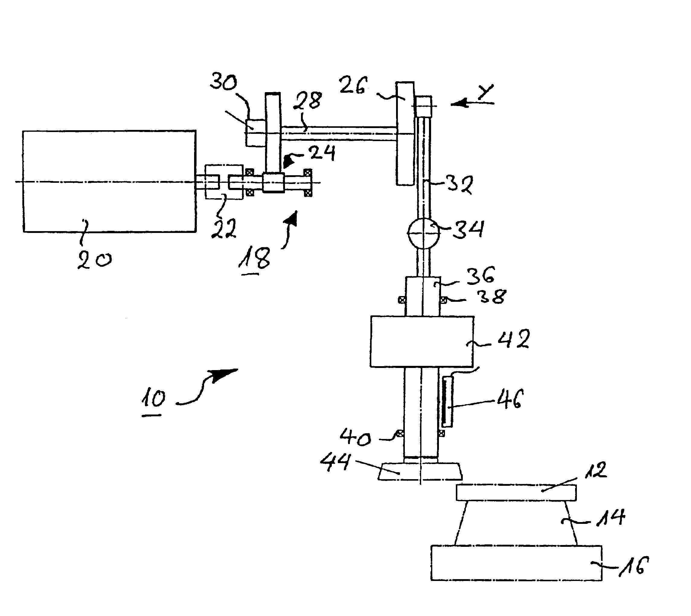
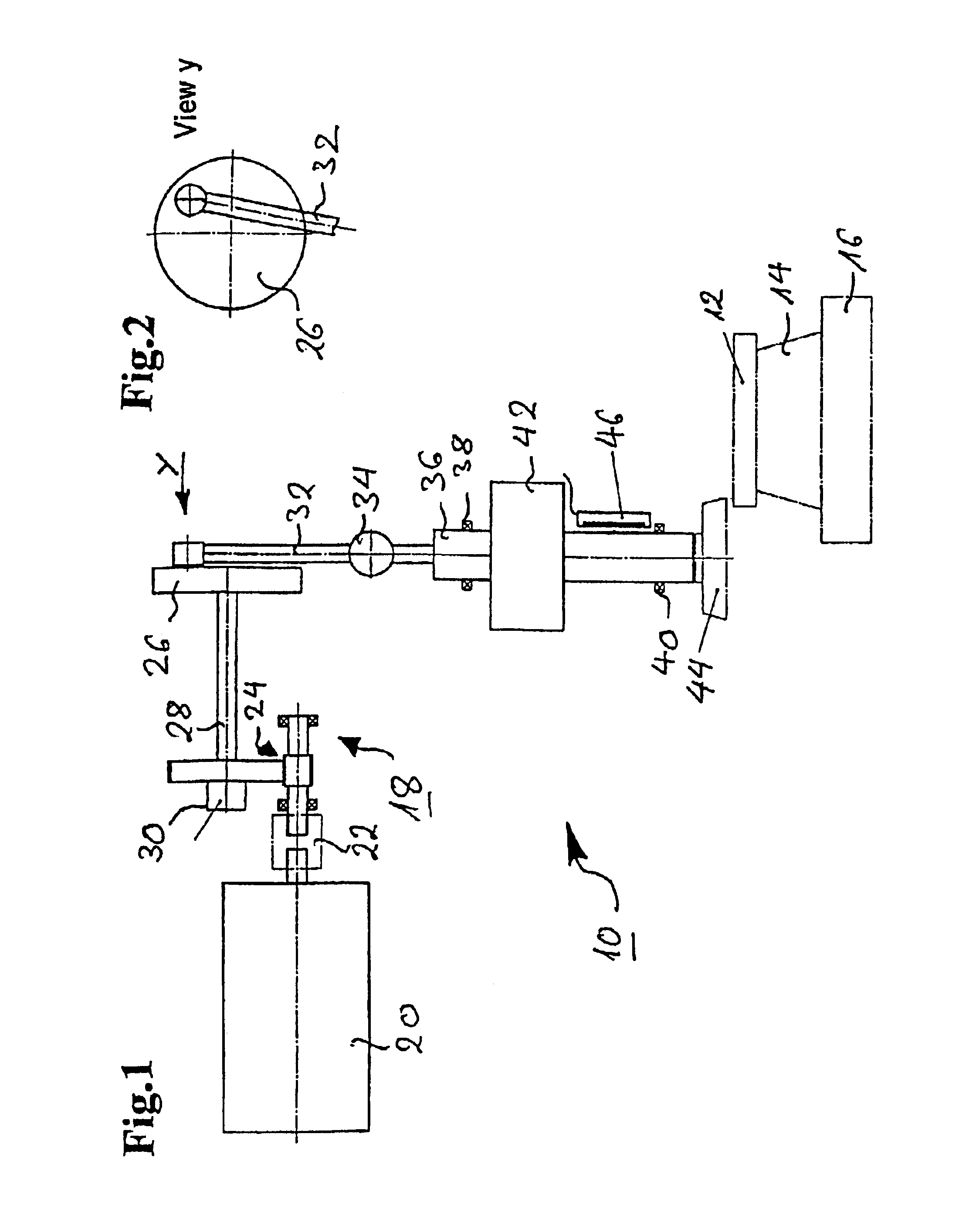
[0018]With the form of embodiment represented in FIG. 1 of gear shaping machine 10 according to the invention, a work-piece 12, from which a gear wheel is to be produced, is clamped on a machine table 14. Machine table 14 is rotatable by means of a drive 16, whereby drive 16 can be provided as a direct drive or as a motor gear unit.

[0019]Gear shaping machine 10 has a stroke drive 18, which here consists of a motor 20, which is in operative connection with a cam gear 26 via a coupling 22 and a toothed wheel gearing 24. An angle measuring device 30 is arranged on shaft 28 of cam gear 26. Angle measuring device 30 serves as a so-called first measuring device.

[0020]Rotatably linked to cam gear 26 is a transmission linkage 32, which is connected to a thrust spindle 36 via a further hinge joint 34. Thrust spindle 36 is mounted in a rotary manner about its symmetrical axis in the stroking direction and in the rotation direction, which is indicated here by bearings 38 and 40.

[0021]Thrust sp...


PUM

PropertyMeasurementUnit
areaaaaaaaaaaa
angle measuringaaaaaaaaaa
angle of rotationaaaaaaaaaa

Abstract

The invention relates to a gear shaping machine for the production, or more precisely machining, of gear wheels with a motor-driven rotatable machine table for holding the work-piece, a thrust spindle with a tool fixed thereto, preferably a cutting wheel, the thrust spindle being displaceable in a selective stroking and superimposed rotary motion, whereby the stroke position can be detected by a first measuring device arranged in the stroke drive, and to a method for the operation of the aforementioned gear shaping machine. The superimposed rotary motion of the thrust spindle is produced via a direct rotary drive and there is arranged in the area of the thrust spindle a second measuring device for the detection of errors in its movement path.

Description

BACKGROUND OF THE INVENTION[0001]The invention relates to a gear shaping machine for the production, or more precisely machining, of gear wheels with a motor-driven rotatable machine table for holding the work-piece and a thrust spindle with a tool fixed thereto, e.g. a cutting wheel, said thrust spindle being displaceable in a selective stroking and superimposed rotary motion, whereby the stroke position can be detected by a first measuring device arranged in the stroke drive.[0002]With such gear shaping machines, the work-piece to be machined and the thrust tool perform a rotary motion during the production, or more precisely machining, of gear wheels. The rotation axes of the work-piece and of the cutting tool arranged on the thrust spindle are preferably arranged parallel to one another in the production of cylindrical work-pieces. A preferably linear stroking motion in the direction of the axis of the tool for the metal removal is superimposed here on the rotation of the thrust...

Claims


Application Information

Patent Timeline
Patent Type & Authority Patents(United States)
IPC IPC(8): B23F5/12B23F5/00B23F23/12F16H21/20F16H21/22F16H25/20F16H55/17
CPCB23F5/12Y10T409/101431Y10T409/104293Y10T409/104134Y10T409/105088Y10T409/100159
Inventor SCHUON, JOACHIM
Owner LIEBHERR VERZAHNTECHNIK GMBH
Why Eureka
Try Eureka