Bending control mechanism for endoscope

a control mechanism and endoscope technology, applied in the field of endoscopes, can solve the problems of inability to control the bending control lever at a uniform turning torque, and the control lever requires a greater force for controlling, so as to achieve the effect of maximizing the tension applied to the driving wire wound round the pulley, small force and improved controllability of the endoscop

Inactive Publication Date: 2005-06-14
FUJI PHOTO OPTICAL CO LTD
View PDF5 Cites 11 Cited by
  • Summary
  • Abstract
  • Description
  • Claims
  • Application Information

AI Technical Summary

Benefits of technology

[0011]According to the invention like this, in the state where the tension applied to the driving wire wound round the pulley connected with the bending control lever is maximized while the bending portion control is carried out, as the extending direction of the driving wire is substantially in parallel with the guide surface of the guide member guiding the driving wire, there is no need for any excess force to be used for winding up the driving wire round the pulley by using the bending control lever, and the bending portion can be controlled with smaller force, whereby the controllability of the endoscope is improved.
[0012]Furthermore, in the state where the tension applied to the driving wire wound round the pulley is maximized while the bending portion control is carried out, as the driving wire is substantially in parallel with the guide surface of the guide member, it becomes possible to prevent the consumption or frictional wear of the driving wire caused by the rubbing motion between the driving wire and the wall face of the driving wire winding groove, which take place when winding the driving wire round the pulley. Consequently, there is improved the durability of the driving wire wound round the pulley of the bending control mechanism. With this, durability of the driving wire can be improved.

Problems solved by technology

However, if the winding diameter of the pulley is made large, the turning torque of the pulley becomes large, which causes such inconvenience that the bending control lever requires greater force for controlling it.
Because of this, the turning torque of the pulley gradually becomes larger corresponding to the number of turns of the driving wire, whereby bending control at a uniform turning torque becoming impossible.

Method used


Image

  • Bending control mechanism for endoscope
  • Bending control mechanism for endoscope
  • Bending control mechanism for endoscope

Examples


first embodiment

(First Embodiment)

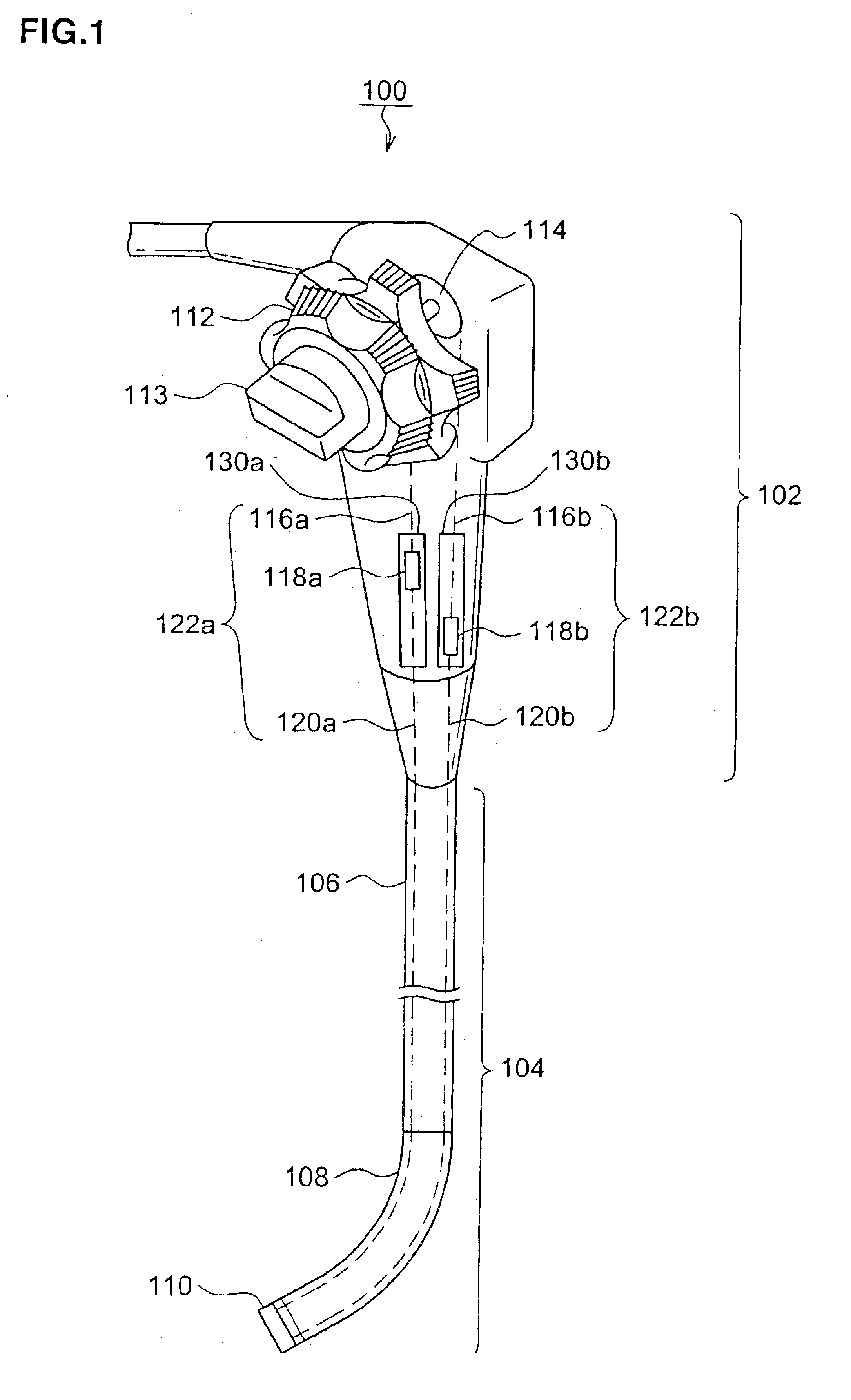
[0030]First of all, there will be described an endoscope according to the first embodiment of the invention with reference to FIG. 1, which indicates the whole constitution of an endoscope according to the first embodiment of the invention. As shown in this figure, an endoscope 100 is composed of two principal portions, of which one is a control portion 102 and the other is a flexible insertion portion 104 connected with the control portion 102 and is inserted in the somatic cavity. The insertion portion 104 includes a flexible soft portion 106 connected with the control portion 102, a bend-free bending portion 108 connected with at the tip side of the soft portion 106, and a hard tip distal end portion 110 which is provided with an objective window (lens) and is connected with the tip of the bending portion 108.

[0031]In the control portion 102 of the endoscope 100, there is provided a bending control mechanism for controlling the bending of the above bending porti...

second embodiment

(Second Embodiment)

[0061]The following describes the bending control mechanism of the endoscope according to the second embodiment of the invention with reference to the accompanying drawings. FIGS. 9A and 9B are diagrams schematically showing the constitution and the operation of the bending control mechanism for the endoscope according to the second embodiment of the invention, in which FIG. 9A indicates the bending control mechanism staying in the neutral state (non-bending control) while FIG. 9B indicates the bending control mechanism staying in the state where the most driving wire 116 is wound round the pulley 214. The endoscope to which the bending control mechanism of this embodiment is applied is the same as the one described in the first embodiment. Thus a detailed explanation thereof has been omitted. This omission will be applied to the other embodiments as will be described later.

[0062]As shown in FIG. 9B, in the state where the most driving wire 116 is wound round the ...

third embodiment

(Third Embodiment)

[0070]The following describes the bending control mechanism for the endoscope according to the third embodiment of the invention with reference to the accompanying drawings. FIGS. 10A and 10B are diagrams schematically showing the constitution and the operation of the bending control mechanism for the endoscope according to the third embodiment of the invention, in which FIG. 10A indicates the bending control mechanism when it stays in the neutral state, and FIG. 10B indicates the state of the bending control mechanism when the most driving wire 116 is wound round the pulley 314.

[0071]In the bending control mechanism according to the third embodiment as shown in FIGS. 10A and 10B, there is provided a pulley displacement mechanism, which enables a pulley 314 to move up and down in the axial direction thereof such that the extending direction of the driving wire 116 becomes substantially parallel to the guide face of the guide member 130 in correspondence with the he...


PUM


Abstract

Disclosed is a bending control mechanism for an endoscope according to the invention, which is characterized in that the bending control mechanism includes a bending portion provided in an insertion portion of the endoscope; a bending wire extended out from the bending portion in order to control the bending portion; a pulley as made operable in link with a bending control lever through the shaft portion of the pulley, the bending control lever being provided in the control portion of the endoscope; a driving wire winding groove as spirally formed on the outer peripheral surface of the pulley as well as in the peripheral direction of the pulley; a driving wire wound around the driving wire winding groove of the pulley; a connection member connecting the driving wire with the bending wire; and a guide member provided in the control portion and including a connection member slidably mounted thereon, wherein in the state where the most driving wire is would round the pulley, a relative position between the pulley and the guide member is determined such that the extending direction of the driving wire is substantially in parallel with the guide surface of the guide member. With the constitution of the above bending control mechanism, there is no need for any excess force to be used for winding up the driving wire round the pulley by using the bending control lever, and it become possible to control the bending portion with smaller force. Thus, controllability of the endoscope is improved and also, durability of the driving wire is improved.

Description

BACKGROUND OF THE INVENTION[0001]The present invention relates to an endoscope for medical use and, more particularly, to a bending control mechanism which is built in the endoscope.[0002]In general, the endoscope is composed of two main portions, of which one is a control portion and the other is a flexible insertion portion connected with the control portion and is inserted in the somatic cavity. The insertion portion includes a flexible soft portion connected with the control portion, a bent-free bending portion connected with the soft portion on the tip side of it, and a hard tip distal end portion which includes an objective window (lens) and others, is connected with the tip of the bending portion.[0003]The endoscope is provided with a bending control mechanism for controlling the bending of the bending portion. This bending control mechanism includes a bending control lever, a pulley of which the rotational motion is controlled by the control lever, and a driving wire wound r...

Claims


Application Information

Patent Timeline
Patent Type & Authority Patents(United States)
IPC IPC(8): A61B1/005G02B23/24A61B1/00
CPCG02B23/2476A61B1/0052
Inventor HINO, KAZUHIKO
Owner FUJI PHOTO OPTICAL CO LTD
Why Eureka
Try Eureka