Component testing system vacuum ring and test plate construction

Inactive Publication Date: 2005-06-14
CERAMIC COMPONENT TECH
View PDF8 Cites 29 Cited by
  • Summary
  • Abstract
  • Description
  • Claims
  • Application Information

AI Technical Summary

Benefits of technology

[0016]Thus, the invention provides an improved vacuum ring and test. plate construction such that the vacuum ring and test plate are more abrasion resistant, the vacuum ring is more arc-over proof, and

Problems solved by technology

The tiny size of electronic circuit components of interest herein complicates processing.
Typically fabricated of ceramic material in parallelepiped shapes having dimensions as small as 0.020″ by 0.010″ by 0.010″ more or less, these difficult-to-handle components require appropriate equipment and pr

Method used


Image

  • Component testing system vacuum ring and test plate construction
  • Component testing system vacuum ring and test plate construction
  • Component testing system vacuum ring and test plate construction

Examples


Embodiment Construction

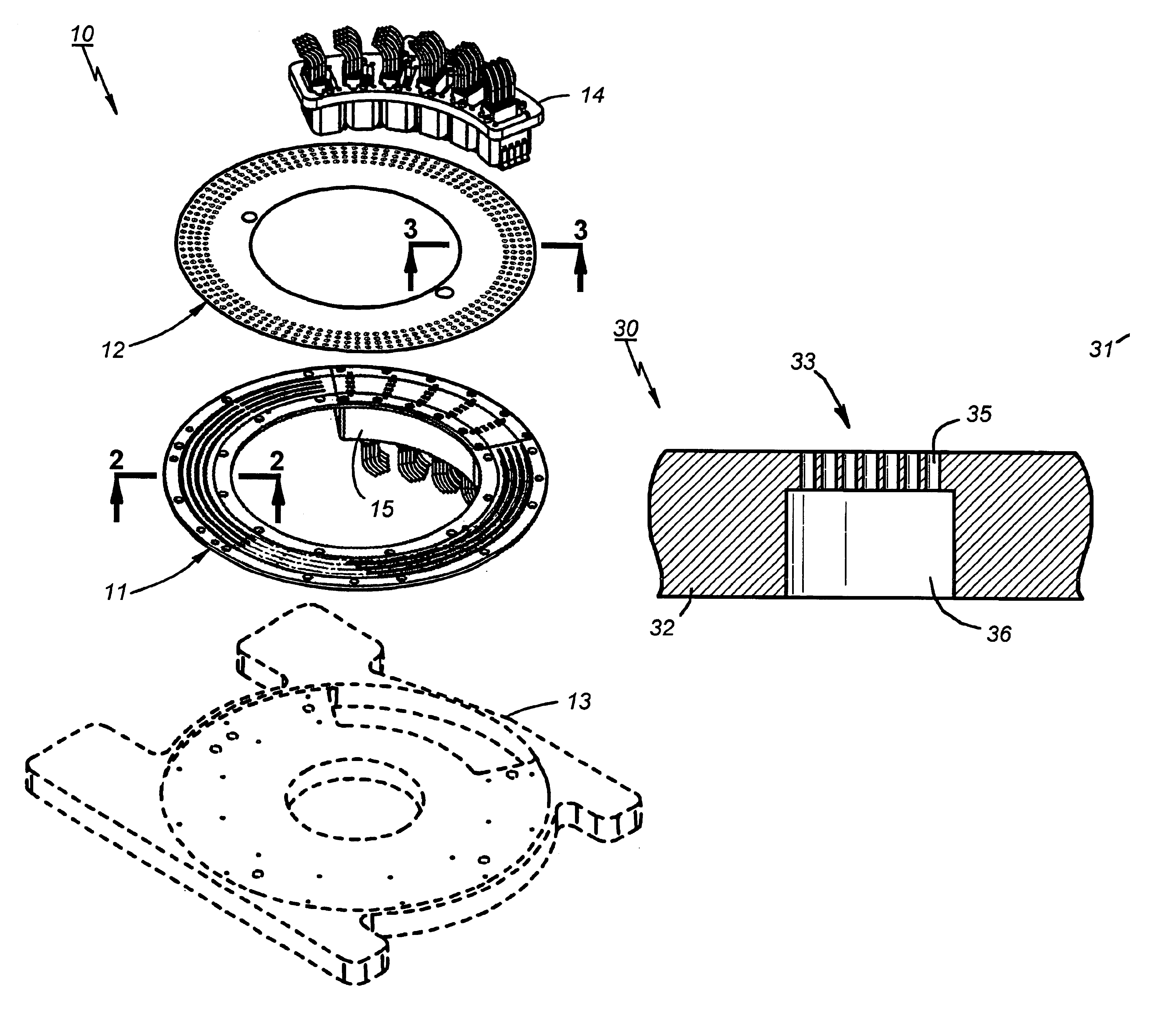
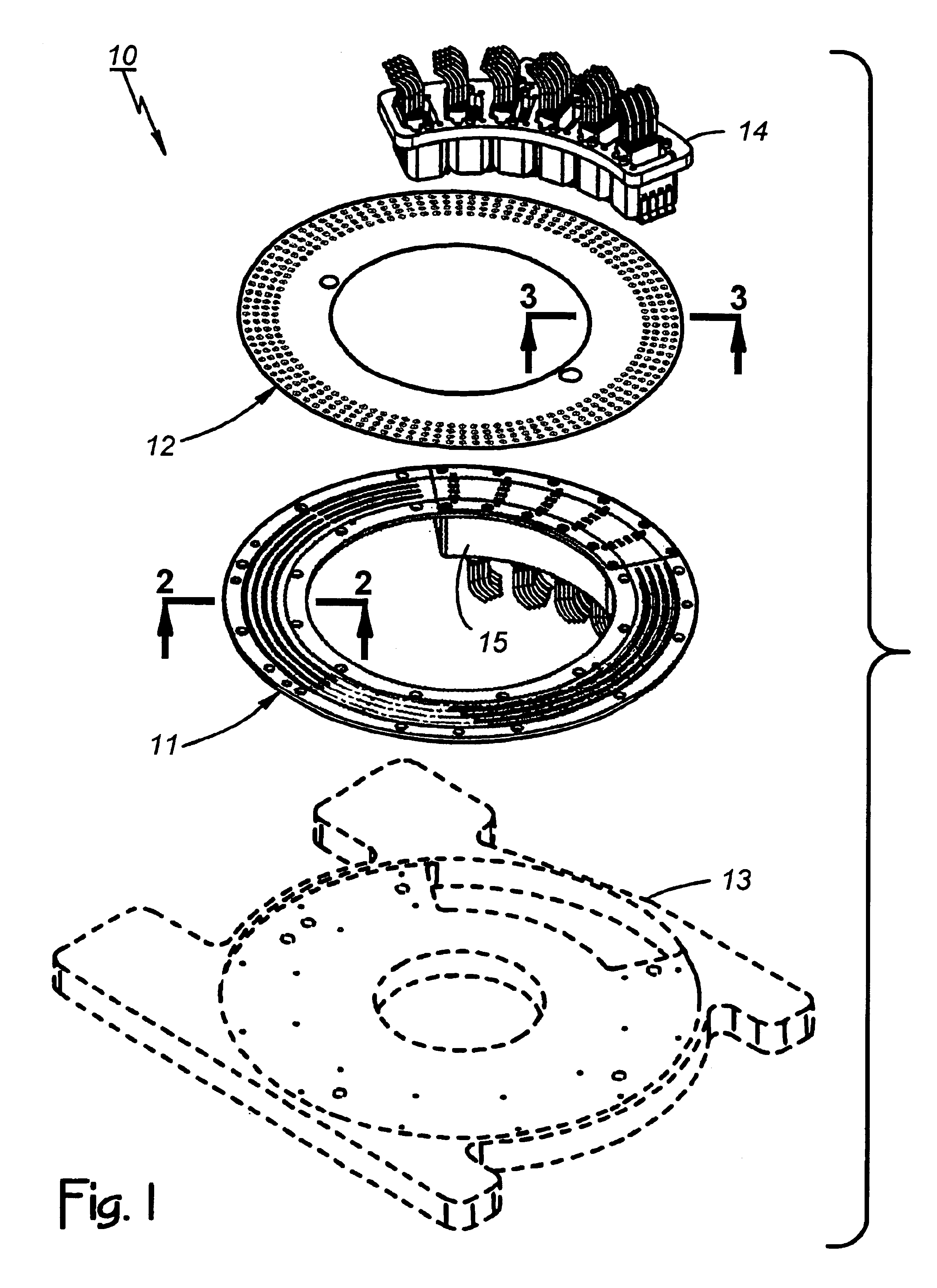
[0025]FIG. 1 of the drawings shows a component testing system 10 that includes a vacuum ring 11 (a vacuum-communicating part) and a test plate 12 (a component-holding part) that are constructed according to the invention. The testing system 10 is similar in some respects to the testing machine described in U.S. Pat. No. 6,194,679 and the testing machine in that patent is similar in some respects to the testing machine available from Electro Scientific Industries, Inc. (ESI) of Portland, Oreg. as its model ESI-3300.

[0026]The component testing system 10 includes what is sometimes called a base plate 13 on which the vacuum ring 11 is mounted. The test plate 12 mounts rotatably over the vacuum ring 11 where it functions as means for receiving and hold a batch of DUTs. The vacuum ring 11 operates in conjunction with the test plate 12 in a known way to couple a vacuum source (not shown) on the component testing system 10 to the test plate 12 and DUT-holding holes in the test plate 12.

[002...


PUM


Abstract

A vacuum ring on a component testing system includes a metallic base material defining a vacuum-communicating passageway. A ceramic layer on the base material, preferably 20-100 micrometers thick and formed by a micro-arc oxidation process resulting in molecular adhesion, improves abrasion resistance and makes the vacuum ring more arc-over proof. A test plate for holding DUTs includes such a ceramic layer that provides better wear while enabling use of the base as a guard layer during testing. Another aspect of the invention concerns a vacuum ring having an eject hole pattern for discharging compressed gas toward DUTs in order to eject DUTs from a test plate. The eject hole pattern includes a plurality of closely spaced apart holes, each measuring less than the size that would be large enough to receive a DUT having the predetermined minimum cross sectional area.

Description

BACKGROUND OF THE INVENTION[0001]1. Technical Field[0002]This invention relates generally to the batch processing of miniature electronic circuit components, including passive, two-terminal, ceramic capacitors, resistors, inductors, and the like. More particularly, it concerns a vacuum ring and a test plate that are used on a component testing system for holding such components or other type of device under test (DUT) as part of the batch processing for purposes of parametric testing.[0003]2. Description of Related Art[0004]The tiny size of electronic circuit components of interest herein complicates processing. Typically fabricated of ceramic material in parallelepiped shapes having dimensions as small as 0.020″ by 0.010″ by 0.010″ more or less, these difficult-to-handle components require appropriate equipment and precision handling techniques. During testing, such a component is sometimes referred to as a device under test (DUT).[0005]U.S. Pat. No. 6,194,679 describes a testing m...

Claims


Application Information

Patent Timeline
IPC IPC(8): G01R1/00G01R31/02
CPCG01R31/013
Inventor SAULNIER, CHRISTIAN R.GASQUE, JAMES G.
Owner CERAMIC COMPONENT TECH
Why Eureka
Try Eureka