
Apparatus and method to detect moisture

a technology of moisture detection and apparatus, applied in the direction of instruments, material impedance, weighing by absorbing components, etc., can solve the problems of contaminated electrical insulation, common leakage of water, catastrophic failure, etc., and achieve accurate and practical effects

Active Publication Date: 2005-06-14
D J GEISEL TECH INC 50 +1
View PDF12 Cites 41 Cited by
  • Summary
  • Abstract
  • Description
  • Claims
  • Application Information

AI Technical Summary

Benefits of technology

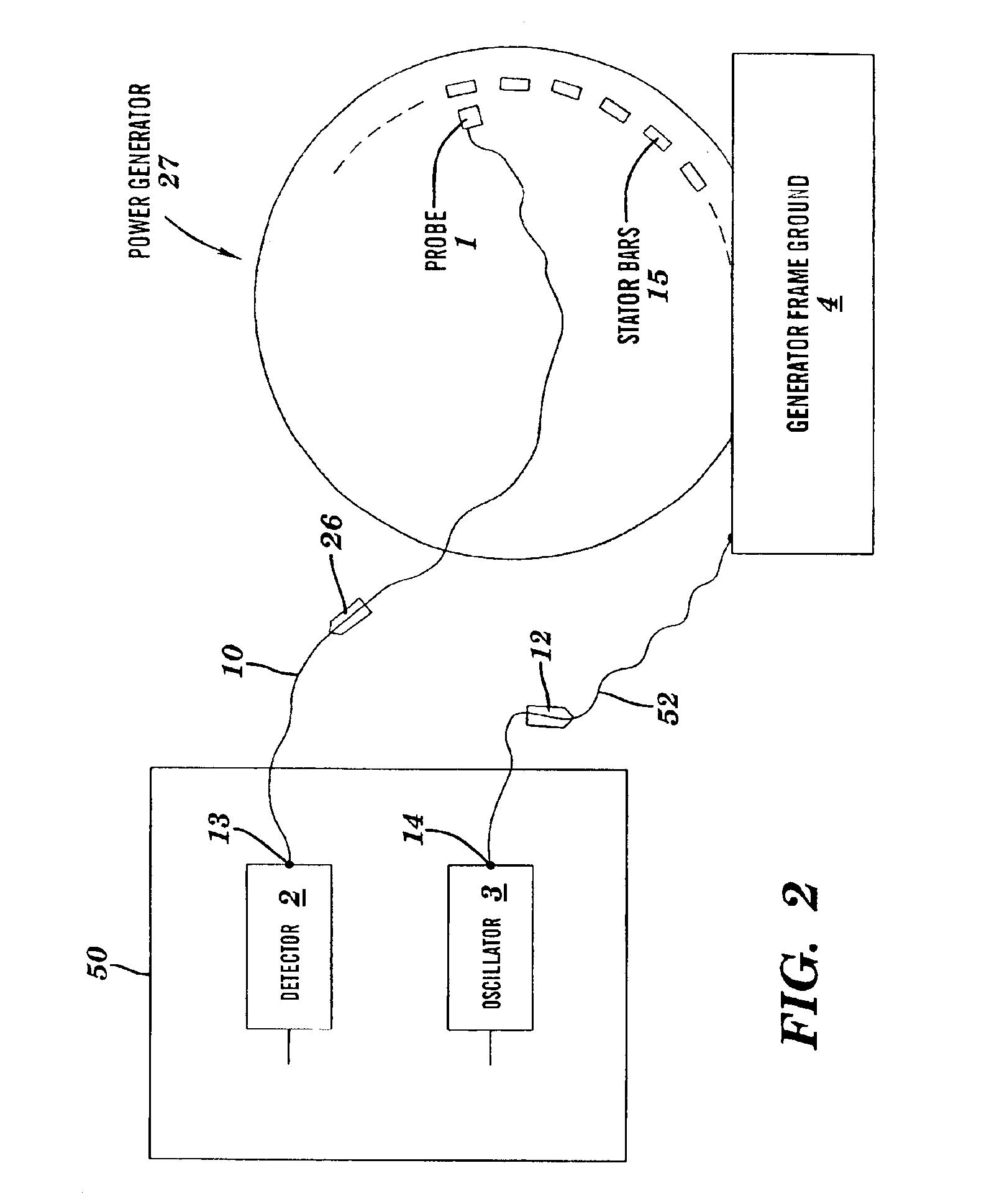
[0024]The present invention provides a more accurate and practical method and apparatus for detecting moisture at an early stage, wherein the moisture is due to water leaks in a power generator.

Problems solved by technology

Although this flowing water removes excessive heat, water leaks are common due to nearly a hundred stator bars in a mega-watt generator.
The leaking water contaminates the electrical insulation, which surrounds the stator bar.
These leaks can eventually cause a catastrophic failure.
The ensuing failure could cause significant damage to the generator as well as lost revenue and customers may consequently experience loss of power or reduced power.
Some of the methods of detecting moisture in stator bars include visual inspection, gas leak testing, electrical hi-potting and capacitance mapping, each of which has disadvantages due to innacuracy and / or other difficulties.

Method used


Image

  • Apparatus and method to detect moisture
  • Apparatus and method to detect moisture
  • Apparatus and method to detect moisture

Examples


Embodiment Construction

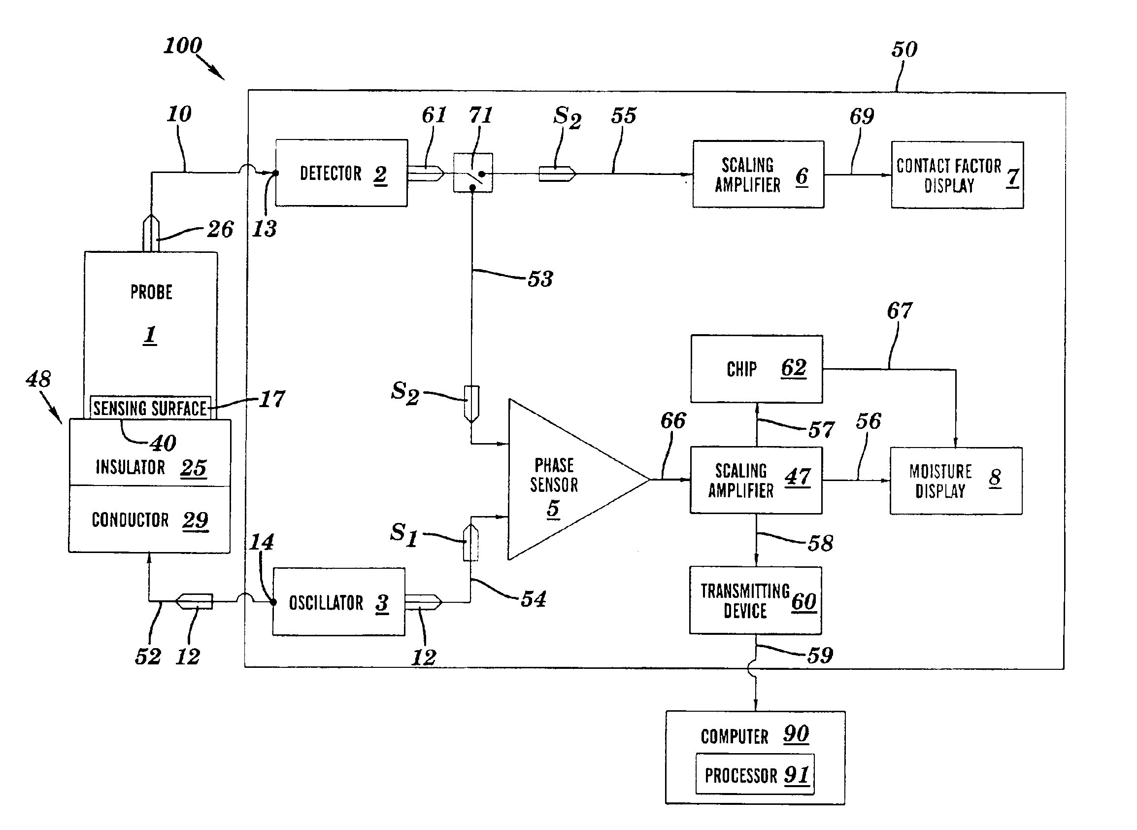
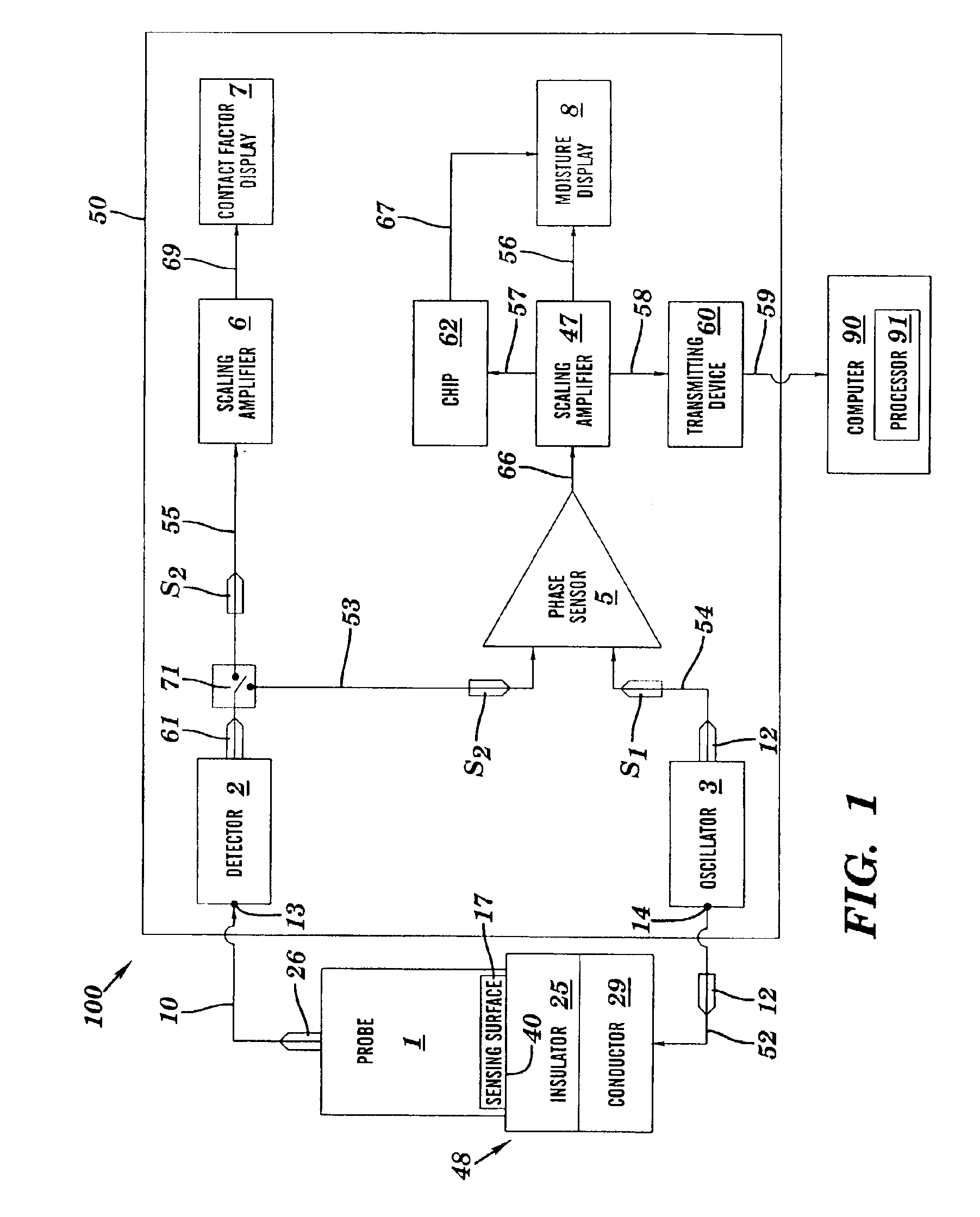
[0042]Dry and moist insulation has substantially different dielectric properties. The apparatus of the present invention can measure these properties and display both magnitude and phase of an electrical signal passing through the stator bar insulation. The phase of the signal is a good indication of moisture contamination. In electrical circuit theory, a pure insulator causes a 90 degree phase shift; i.e., the current leads the applied voltage by 90 degrees. A moist or lossy insulator will cause a several degree “off” 90 phase shift, such as 85 degrees. For simplicity, this disclosure will work with positive phases and phase shifts and will therefore assume, for a given insulation, that a signal has a reference phase of zero degrees when propagating through the given insulation in a purely dry state. Thus, a phase of zero degrees corresponds to a phase shift between the voltage and current of exactly 90 degrees. The same signal is phase shifted so as to acquire a phase of a few deg...


PUM


Abstract

A method and apparatus for detecting moisture. An oscillatory electrical signal S1 generated by an oscillator is propagated into a body that includes an electrically insulative material. A signal due to S1 emerges from the body as an oscillatory electrical signal S2. The signals S1 and S2 differ in phase by Δφ, wherein Δφ is indicative of moisture along a path traversed by S1 within the insulative material, and wherein the conductance σ of the insulative material is also indicative of the moisture along the path traversed by S1 within the insulative material. S2 is received at a sensing surface of a sensing part (e.g., probe, sensing antenna, etc.) and then transmitted to a moisture detecting device. The moisture detecting device determines from S1 and S2 a measure M of the moisture as a function of Δφ or as a function of σ.

Description

RELATED APPLICATION[0001]The present invention claims priority to U.S. Provisional Application No. 60 / 384,500, filed on May 30, 2002, which is incorporated herein by reference in its entirety.BACKGROUND OF THE INVENTION[0002]1. Technical Field[0003]The present invention relates to a method and apparatus for detecting moisture, and more particularly to a method and apparatus for detecting moisture in an electrically insulative portion of a body of mass.[0004]2. Related Art[0005]Large power generators can be water cooled by allowing the water to flow through the stator bars. Although this flowing water removes excessive heat, water leaks are common due to nearly a hundred stator bars in a mega-watt generator. The leaking water contaminates the electrical insulation, which surrounds the stator bar. These leaks can eventually cause a catastrophic failure. The ensuing failure could cause significant damage to the generator as well as lost revenue and customers may consequently experience...

Claims


Application Information

Patent Timeline
IPC IPC(8): G01N27/04G01N27/02G01N27/22
CPCG01N27/048G01N27/045
Inventor GEISEL, DONALD J.
Owner D J GEISEL TECH INC 50
Learn More