
Methods and apparatus for testing a circuit board using a surface mountable adaptor

Inactive Publication Date: 2005-06-14
CISCO TECH INC
View PDF2 Cites 20 Cited by
  • Summary
  • Abstract
  • Description
  • Claims
  • Application Information

AI Technical Summary

Benefits of technology

[0007]Also, as described above, the bed of nails tester is relatively large and heavy. The size and weight of the bed of nails tester limits the practicality or the possibility for an operator to test a circuit board in its normal operating environment and under normal operating conditions (e.g., mounted within a card cage with neighboring circuit boards). For example, in the case of the computer system having multiple circuit boards, the conventional card cage limits the distance or space (e.g., slot) between adjacent circuit boards. Conventional bed of nails testers are relatively large and are not configured to fit within the slot between adjacent circuit boards.
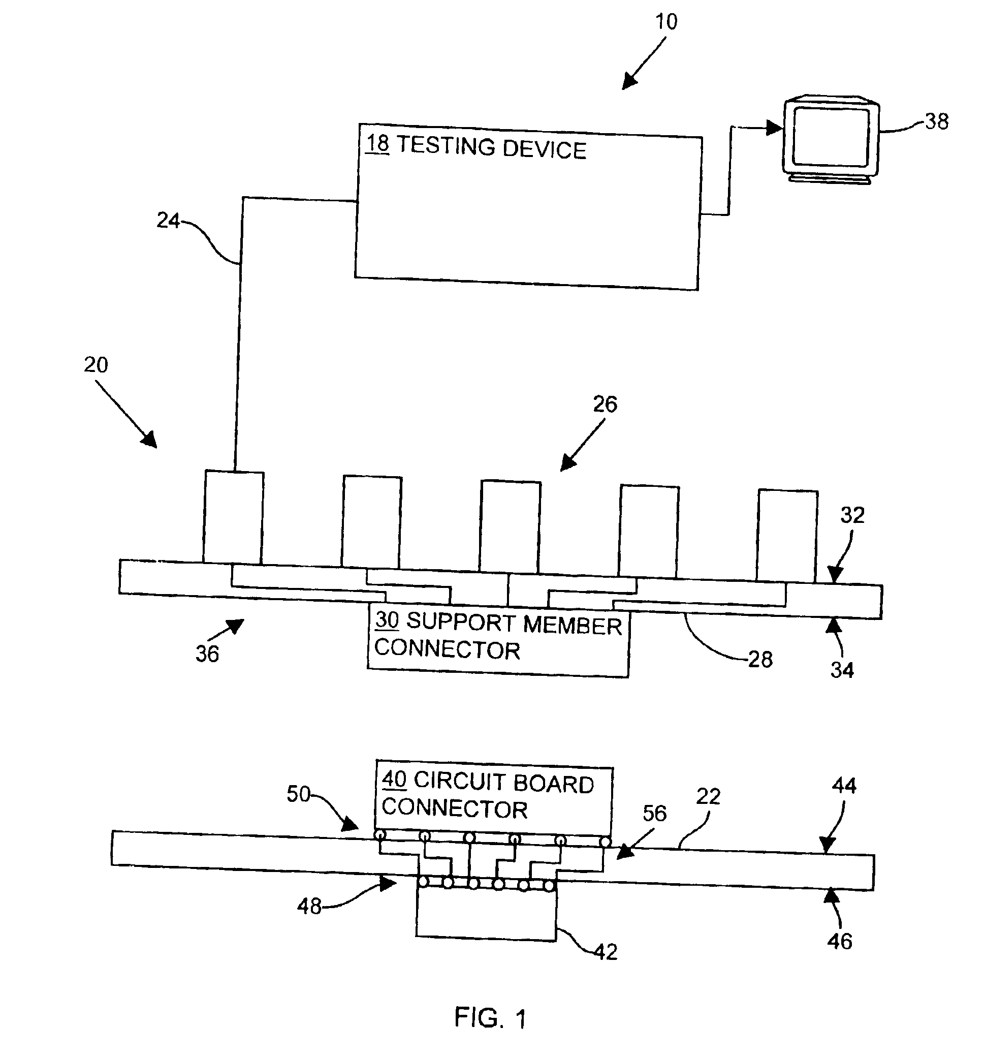
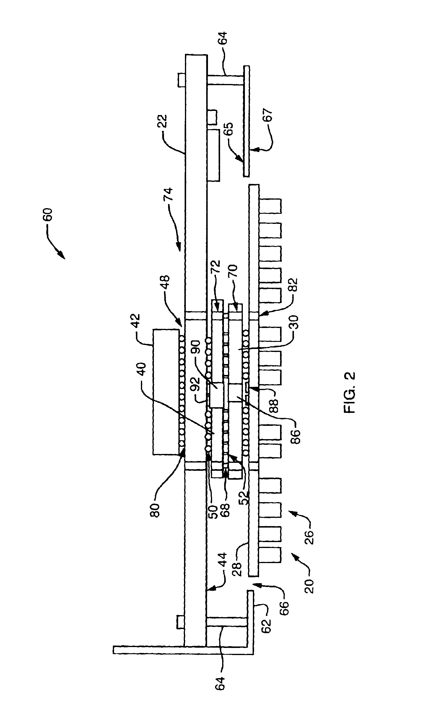
[0021]Another embodiment of the invention relates to a circuit board testing assembly having a support member having a first surface and a second surface, at least one debugging connector coupled to the first surface of the support member where the at least one debugging connector is configured to attach to a circuit board testing device, a circuit board component coupled to the first surface of the support member and in electrical communication with the at least one debugging connector, and a support member connector coupled to the second surface of the support member and in electrical communication with the at least one debugging connector. The support member is configured to removably attach to a circuit board connector mounted to a first surface of a circuit board. The support member connector, the circuit board connector and the debugging connector are configured to provide a set of electrical connections from the circuit board to the testing device when support member connector connects with the circuit board connector and the debugging connector connects with the testing device. Removable attachment of the debugging connectors to the circuit board provides an availability of space on the top side of the circuit board for additional circuit board components and traces, thereby allowing for an increase in the performance of the circuit board.

Problems solved by technology

Conventional testing devices and techniques for testing a circuit board suffer from a variety of deficiencies.
Because the bed of nails tester requires the circuit board to be removed from its operating environment, the use of the bed of nails device for the circuit board described is impractical.
Also, as described above, the bed of nails tester is relatively large and heavy.
The size and weight of the bed of nails tester limits the practicality or the possibility for an operator to test a circuit board in its normal operating environment and under normal operating conditions (e.g., mounted within a card cage with neighboring circuit boards).
Conventional bed of nails testers are relatively large and are not configured to fit within the slot between adjacent circuit boards.
Such test pads, however, occupy real estate on the circuit board that can otherwise be available to mount other active components.
The use of the bed of nails tester to test a circuit board having multiple circuit board components, therefore, can limit the amount of usable circuit board real estate.
Real estate (e.g., available space) on the top side (e.g., component side) of printed circuit boards, therefore, is limited.
Mounting of debugging connectors to the top side a circuit board circuit, therefore, can limit the performance of the circuit board.
Many debugging connector designs, however, have a through-hole requirement, which takes away routing space in the inner layers of the printed circuit board and also utilizes real estate on the top side of the circuit board.
Additionally, real estate available for debugging connectors decreases as the size of the circuit board decreases.
While such a configuration provides a user with the ability to test the circuit board after shipment, the debugging connectors add to cost of manufacture for each circuit board.
Also, removable attachment of debugging connectors to the circuit board decreases manufacturing costs associated with the circuit board since the debugging connectors are useable to test and debug multiple circuit boards.
Such misalignment can lead to improper testing of the circuit board or circuit board component.

Method used


Image

  • Methods and apparatus for testing a circuit board using a surface mountable adaptor
  • Methods and apparatus for testing a circuit board using a surface mountable adaptor
  • Methods and apparatus for testing a circuit board using a surface mountable adaptor

Examples


Embodiment Construction

[0032]Embodiments of the present invention provide a method and apparatus for testing a circuit board using a surface mount adaptor, the surface mount adaptor allowing for removable attachment of debugging connectors to the circuit board and providing high density access to the circuit board under test at a single location. Such removable attachment of the debugging connectors provides an availability of space on the top side of the circuit board for additional circuit board components and traces. Also, removable attachment of debugging connectors to the circuit board decreases manufacturing costs associated with the circuit board since the debugging connectors are useable to test and debug multiple circuit boards. Surface mounting the adaptor to the circuit board also minimizes the necessity for using through-holes or support plates to secure the adaptor to the circuit board.

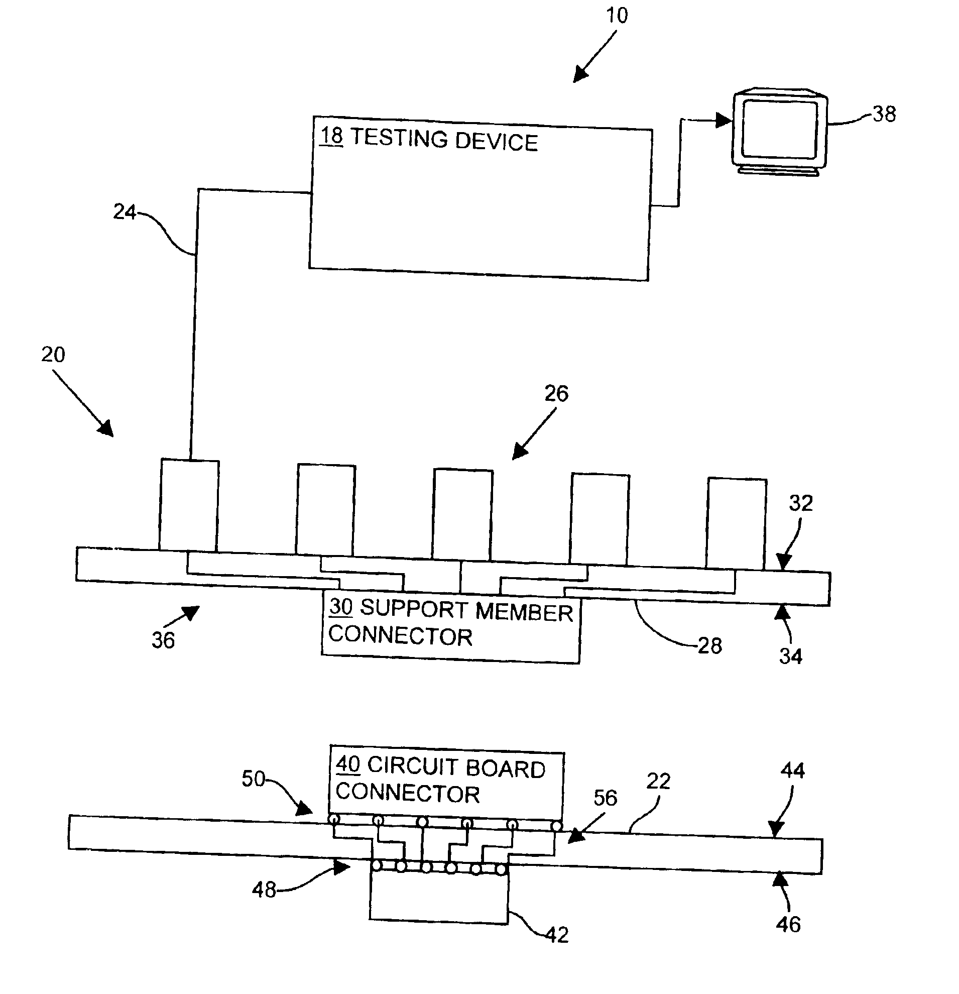
[0033]FIG. 1 illustrates a circuit board testing system 10. In the arrangement shown, the testing system 10 ...


PUM


Abstract

A surface mount adaptor allows for removable attachment of debugging connectors to a circuit board and provides high density access to the circuit board under test at a single location. A circuit board testing assembly has a support member having debugging connectors coupled to a first surface of the support member, the debugging connectors being configured to attach to a circuit board testing device. The circuit board testing assembly also has a support member connector coupled to a second surface of the support member and in electrical communication with the debugging connectors. The support member is configured to removably attach to a circuit board connector surface mounted to a first surface of a circuit board. Removable attachment of the debugging connectors from the circuit board provides an availability of space on the top side of the circuit board for additional circuit board components and traces.

Description

BACKGROUND OF THE INVENTION[0001]A typical circuit board is formed of circuit board material (e.g., fiberglass, copper, vias, etc.) and circuit board components attached or mounted to the circuit board material. Circuit board manufacturers conventionally test the operability of (e.g., debug) a manufactured circuit board prior to high volume manufacturing and shipping of the circuit board to an end user.[0002]One conventional circuit board testing device is a bed of nails testing device. A typical bed of nails testing device includes a relatively heavy and large support plate and a holder having spring-loaded pins configured to make electrical contact with a circuit board during testing. During operation, for example, a user places the circuit board onto the support plate of the bed of nails testing device. The user then activates the testing device, thereby causing the support plate to lift and press the circuit board against the spring loaded test pins of the holder. The test pins ...

Claims


Application Information

Patent Timeline
IPC IPC(8): G01R31/00G01R31/28
CPCG01R31/2808
Inventor SHANKER, BANGALORE J.JONNAVITHULA, SURYAPRAKASHNAGARAJ, ASHWATHCHENG, WHELING
Owner CISCO TECH INC
Learn More