High-speed domino logic with improved cascode keeper

a domino logic and cascode keeper technology, applied in logic circuits, pulse techniques, electrical devices, etc., can solve the problems of significant drawbacks, significant delay in the operation of prior art domino logic circuits, and inability to perform well in high speed and high noise applications, so as to improve the efficiency of space utilization, increase speed, and high noise immunity

a domino logic and cascode keeper technology, applied in logic circuits, pulse techniques, electrical devices, etc., can solve the problems of significant drawbacks, significant delay in the operation of prior art domino logic circuits, and inability to perform well in high speed and high noise applications, so as to improve the efficiency of space utilization, increase speed, and high noise immunity

US6906556B2Inactive Publication Date: 2005-06-14SUN MICROSYSTEMS INC

Image

  • High-speed domino logic with improved cascode keeper
  • High-speed domino logic with improved cascode keeper
  • High-speed domino logic with improved cascode keeper

Examples


Embodiment Construction

[0022]The invention will now be described in reference to the accompanying drawings. The same reference numbers may be used throughout the drawings and the following description to refer to the same or like parts.

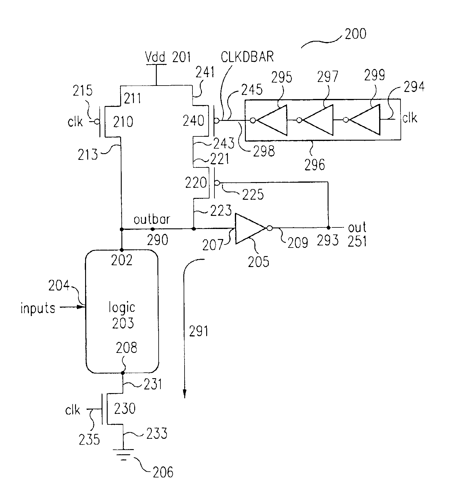
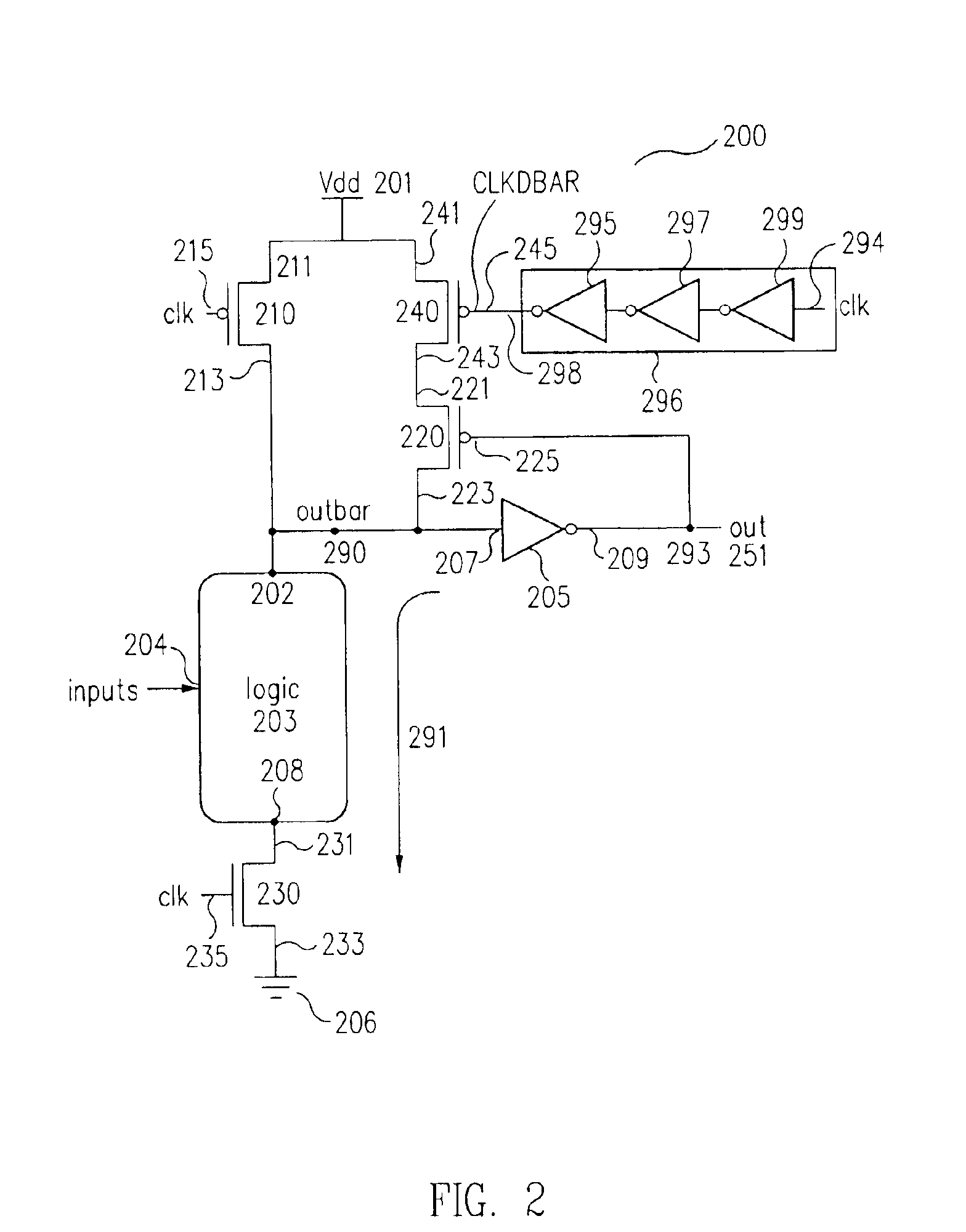
[0023]The high-speed domino logic with improved cascode keeper circuit (200 in FIG. 2) of the invention uses an odd number of inverters (295, 297, 299 in FIG. 2), i.e., one, three, five, seven, etc. inverters, and an additional transistor (240 in FIG. 2) to introduce a transition delay time and node isolation time to avoid the fight between the first node (290 in FIG. 2) and the second, or keeper, transistor (220 in FIG. 2).

[0024]According to the invention, the odd number of inverters create a delayed clock signal CLKDBAR (355 in FIG. 3) that remains a digital “1” for a programmed delay time (330, 331 in FIG. 3), i.e., a one, three, five, seven etc. inverter delay time, while signal CLK immediately transitions to a digital “1” (303 in FIG. 3). During this delay time between...


PUM


Abstract

A high-speed domino logic with improved cascode keeper circuit uses an inverter delay element and an additional transistor to introduce a transition delay time and node isolation time to avoid the contest or “fight” between a first node and the keeper transistor in the event of a path to ground being created through the logic block portion of high-speed domino logic with improved cascode keeper circuit. The high-speed domino logic with improved cascode keeper circuits of the invention, in contrast to prior art domino logic circuits, can be designed to have high noise immunity and increased speed. In addition, since according to the invention, only a minimum of one new inverter and one new are required, the modification of the invention is space efficient and readily incorporated into existing designs.

Description

FIELD OF THE INVENTION[0001]The present invention relates generally to logic circuits and, more particularly, to domino logic circuits.BACKGROUND OF THE INVENTION[0002]FIG. 1 shows a schematic diagram of one embodiment of a typical prior art domino logic circuit 100. As seen in FIG. 1, prior art domino logic circuit 100 included a first supply voltage 101, typically Vdd, coupled to a source, or first flow electrode 111, of a PFET 110 and a source, or first flow electrode 121 of a PFET 120, also known as a keeper transistor. The signal CLK was coupled to a control electrode or gate 115 of PFET 110 and a control electrode or gate 135 of an NFET 130. A drain, or second flow electrode 113, of PFET 110 was coupled to a first node 190. A drain, or second flow electrode 123, of PFET 120 was also coupled to first node 190 and an input terminal 107 of an inverter 105. An output terminal 109 of inverter 105 was coupled to a control electrode or gate 125 of PFET 120 and a prior art domino logi...

Claims


Application Information

Patent Timeline
14 Jun 2005
Publication
US6906556B2
IPC
H03K19/096
CPC
H03K19/0963
Inventors
CHOE, SWEE YEW