Multi-frequency printed antenna

a printed antenna and antenna structure technology, applied in the structural form of the radiating element, the antenna supports/mountings, and the resonance antenna, can solve the problems of poor omnidirectional performance of the planar radiation field pattern and difficulty in matching the impedance with a general symmetrical microstrip, and achieve the effect of easy connection to the feeding signal

Active Publication Date: 2005-06-14
GEMTEK TECH CO LTD
View PDF7 Cites 159 Cited by
  • Summary
  • Abstract
  • Description
  • Claims
  • Application Information

AI Technical Summary

Benefits of technology

[0005]Another object of the present invention is to provide a multi-frequency printed antenna which is light and compact, and is easi

Problems solved by technology

Moreover, the planar radiation field pattern is poor in omnidirectional performance due to the asymmetrical structure, and it is difficult to imp

Method used


Image

  • Multi-frequency printed antenna
  • Multi-frequency printed antenna
  • Multi-frequency printed antenna

Examples


Embodiment Construction

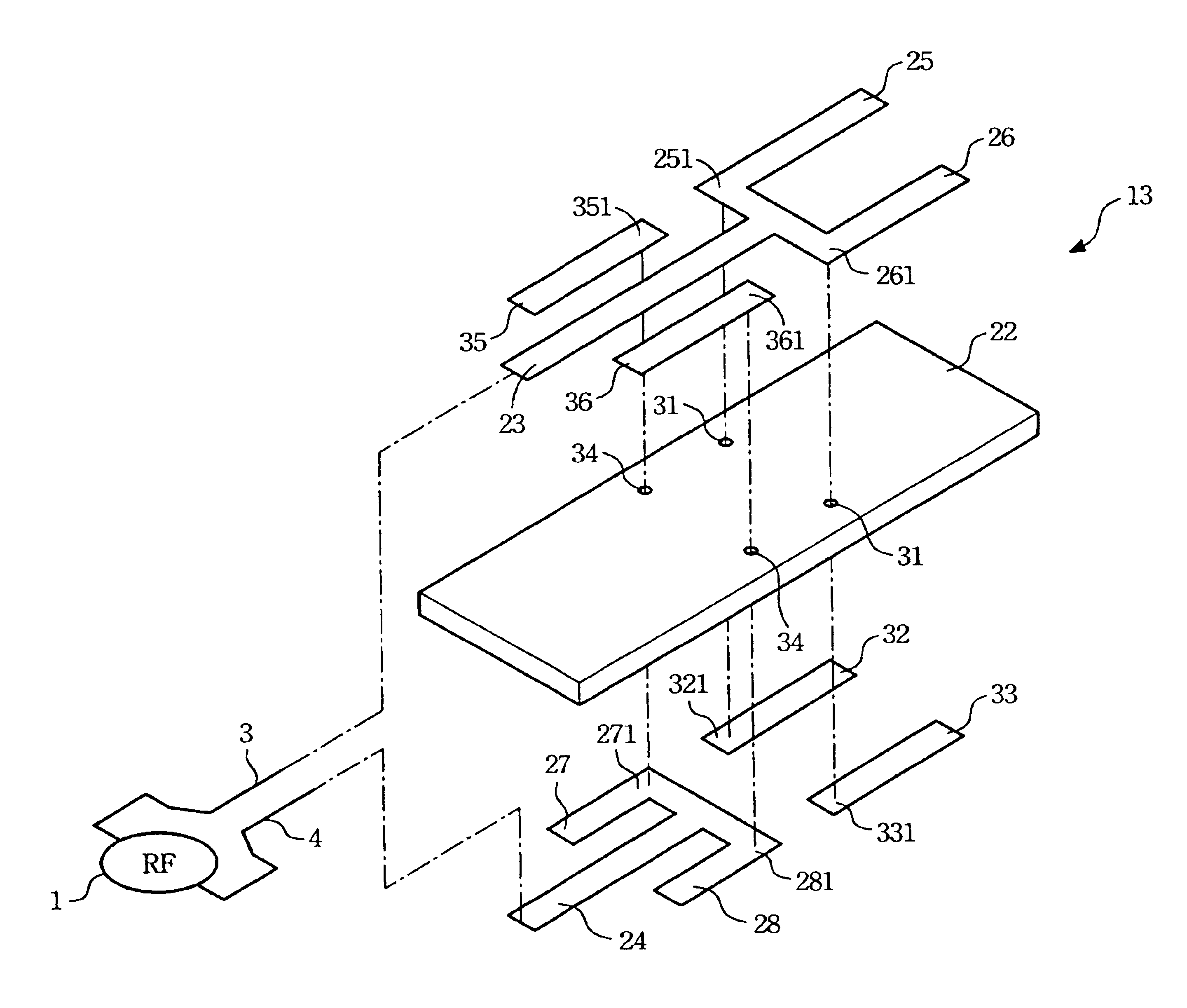
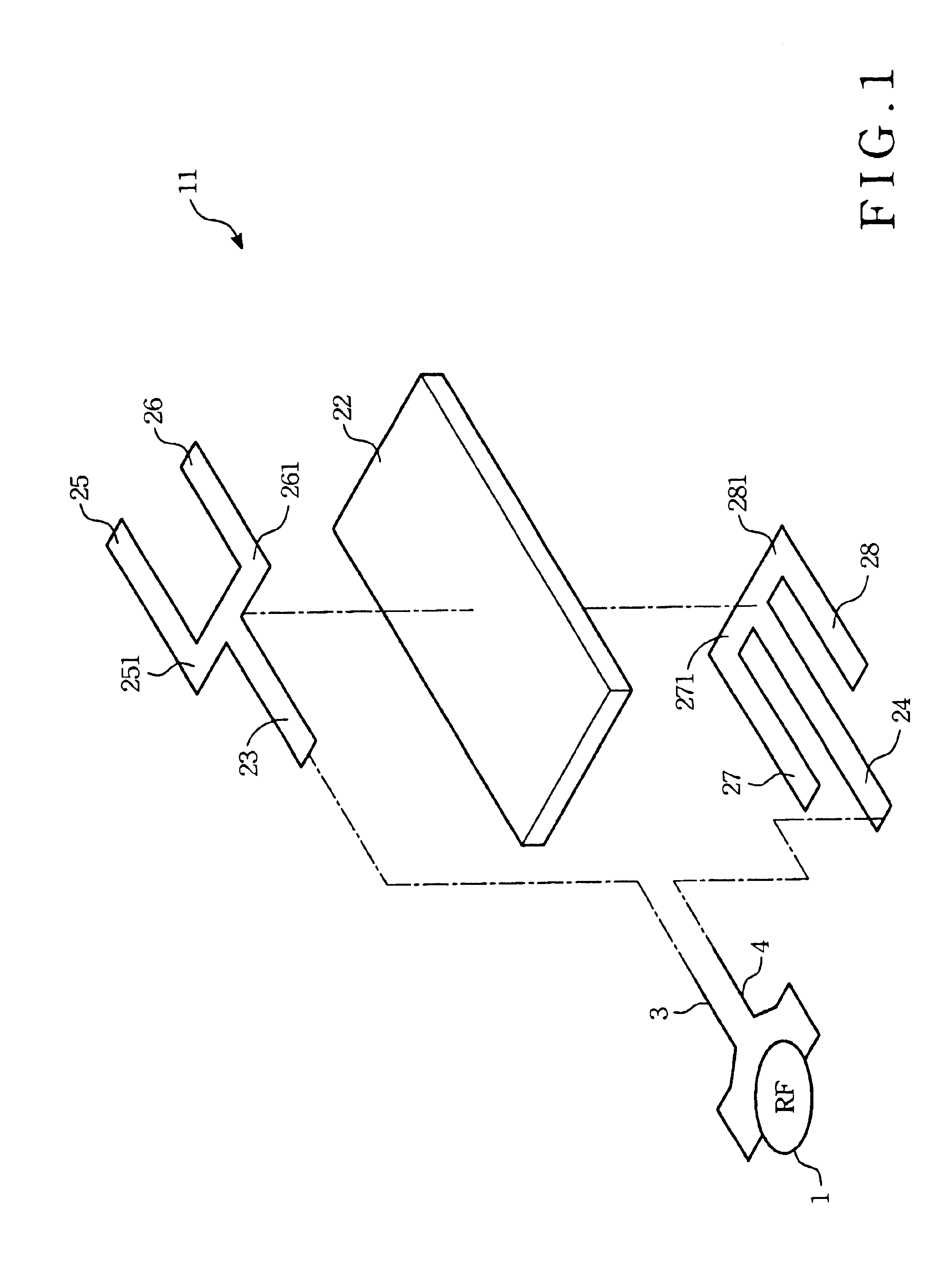
[0013]Please refer to FIG. 1, which is a schematic exploded diagram illustrating a first embodiment of a multi-frequency printed antenna 11 in accordance with this invention. The antenna 11 includes a substrate 22 with an insulating plate structure, a feed strip 23, a ground strip 24, a first radiating conductive strip 25, a second radiating conductive strip 26, a first grounded conductive strip 27, and a second grounded conductive strip 28. The above-mentioned strips are all formed on two opposite surfaces of the substrate 22 in a manner of circuit printing. The substrate 22 is a circuit board made of an insulating material.

[0014]The feed strip 23 is formed on the upper surface of the substrate 22 and extends in a first direction. One end of the feed strip 23 is connected to a signal terminal 3 of a RF signal source 1. The other end of the feed strip 23 is in connection with a connecting portion 251 of the first radiating conductive strip 25 and a connecting portion 261 of the seco...


PUM


Abstract

A multi-frequency printed antenna includes an insulating substrate, a feed strip, a ground strip, and a plurality of radiating and grounded conductive strips. The insulating substrate has a first surface and a second surface opposite to the first surface. The feed strip and the plurality of radiating conductive strips are formed on the first surface while the ground strip and the plurality of grounded conductive strips are formed on the second surface. The radiating conductive strips together with the grounded conductive strips form a multi-resonant mechanism to achieve a multi-frequency antenna radiation.

Description

FIELD OF THE INVENTION[0001]The present invention relates to a compact printed antenna structure and, more particularly, to an antenna structure capable of producing a multi-frequency resonant mechanism for the application of multi-frequency signal transmission.BACKGROUND OF THE INVENTION[0002]With rapid progress of wireless communication technology, mobile communication products have become the mainstream of modern science-and-technology products. These mobile communication products include a notebook computer, a cellular phone, and a personal digital assistant (PDA), etc. After coupling with the wireless communication modules, these products can link to the internet, receive and send electronic mails, and get instant information on news or stocks quotations so as to achieve functions of resource sharing and information transmitting.[0003]A conventional “Printed Sleeve Antenna” disclosed by U.S. Pat. No. 5,598,174 relates to formation of a half wavelength resonant mechanism with ex...

Claims


Application Information

Patent Timeline
IPC IPC(8): H01Q5/00H01Q1/38H01Q9/28H01Q9/04H01Q1/24H01Q5/371
CPCH01Q1/243H01Q5/371H01Q9/285H01Q1/38
Inventor CHEN, TAILEE
Owner GEMTEK TECH CO LTD
Why Eureka
Try Eureka