Further, a normal output apparatus, such as a printer, often outputs a pixel similar to a circle rather than a square pixel due to the process limitations of the apparatus.
Due to this, the image is susceptible to the print position accuracy or the printing accuracy, such as dot size accuracy, of the apparatus.
This sequence is used in a printer, such as a
laser printer and a thermal printer, which tends to be influenced by the appearance state of neighboring pixels and for which it is difficult and unstable to form an image out of independent pixels.
Since the printer of this type is low in resolution, minor print
position error in units of pixels is inconspicuous.
Although it is possible to enhance this printing accuracy to the extent that
image quality is not adversely influenced all, production cost disadvantageously rises.
To completely correct the shifts requires quite high accuracy in mechanical control, which again disadvantageously pushes up cost.
As can be seen, if the
discharge volume and
discharge direction of ink vary with nozzles, concentration becomes uneven, resulting in the deterioration of
image quality.
This method, however, has
disadvantage of delaying printing speed proportionately with the complexity of the printing method.
Further, according to an image forming apparatus capable of expressing one pixel with a plurality of tones by modulating an area for printing one pixel while using multi-level image data, the unevenness of concentration due to printing error is inconspicuous in a relatively highlighted part (i.e., a region having small
diameter dots and low concentration).
However, if an image of a uniform tone level is reproduced on one plane with dots of medium or larger size to the extent that neighboring dots are almost in contact with one another, the unevenness of concentration in the form of stripes becomes particularly conspicuous.
The
reproduction of tones capable of further reducing graininess is one of the most important technical challenges among others.
If a
recording head has the same number of nozzles as that of pixels on a line per color, this disadvantageously leads to cost hike.
Moreover,
color printing is faced by a problem of the unevenness of colors due to slight difference in the overlapping manner of the respective colors of C, M, Y and K. As for the four
color printing of C, M, Y and K, various multi-level
dither methods including dispersion dither methods represented by a halftone dot dither method and a Bayer dither method employing screen angles, a cluster dither method having intermediate characteristics between that of the dispersion dither method and the Bayer dither method and the like, have been developed.
For example, if the halftone dot method employing screen angles is applied to dithering, colors interfere with one another to thereby cause moiré such as roseate moiré.
If a dispersion dither matrix such as a conventional Bayer matrix is employed, conspicuous texture appears at a specific tone part due to the low degree of freedom for the arrangement of dots.
As can be seen, many problems still remain unsolved before obtaining optimum output characteristics over the entire colors or tones.
These problems with dither
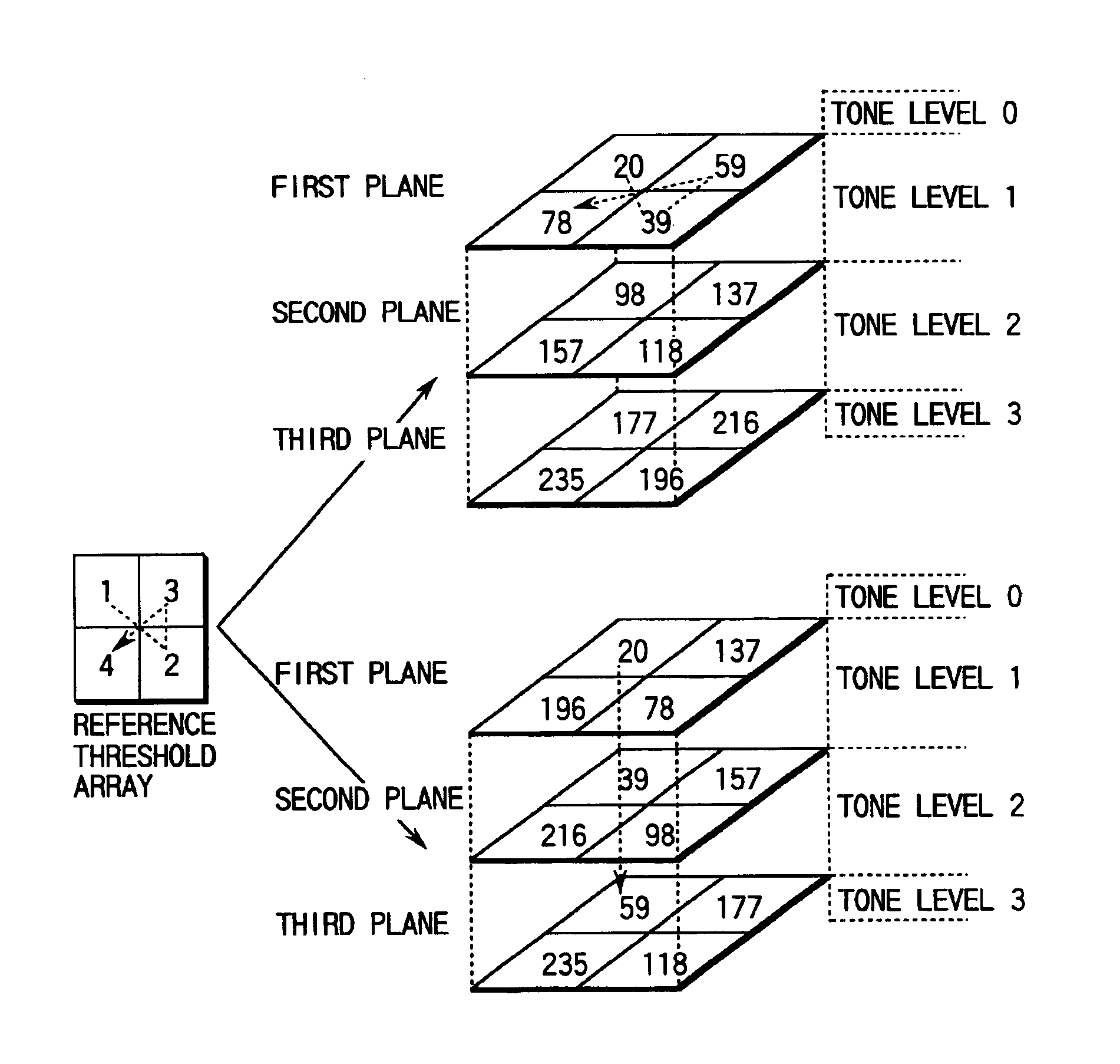
processing occur to both a binary output printer and a multi-level output printer employing a dither matrix.
While the problems are particularly serious in the dither processing of the threshold sequence shown in FIG. 45B, they are not completely solved in the dither processing of the threshold sequence shown in FIG. 45A, either.

