PDA monitoring and diagnostic system for industrial control

a technology of industrial control and diagnostic system, applied in the field of control systems, can solve the problems of increasing the cost of developing such a control system, time-consuming and laborious scenarios, etc., and achieve the effect of easy configuration, easy maintenance and quick maintenance of preset specifications

Inactive Publication Date: 2005-06-14
KAR TECH
View PDF12 Cites 45 Cited by
  • Summary
  • Abstract
  • Description
  • Claims
  • Application Information

AI Technical Summary

Benefits of technology

[0005]The present invention provides for a control system that can be easily configured. With the use of this control device and storage of the different input and output device parameters and their specifications, a person can configure and maintain preset specifications...

Problems solved by technology

This individual configuration scenario for each input and output device is a very time-cons...

Method used


Image

  • PDA monitoring and diagnostic system for industrial control
  • PDA monitoring and diagnostic system for industrial control
  • PDA monitoring and diagnostic system for industrial control

Examples


Embodiment Construction

[0026]The present invention is described as being used with conventional application equipment, such application equipment's usage being known to those of skill in the art. Although the invention is described below in the context of controlling a valve with a joystick type input device (e.g., a valve control assembly), those skilled in the art will recognize that the invention can be employed with, and has applicability to, many different processes.

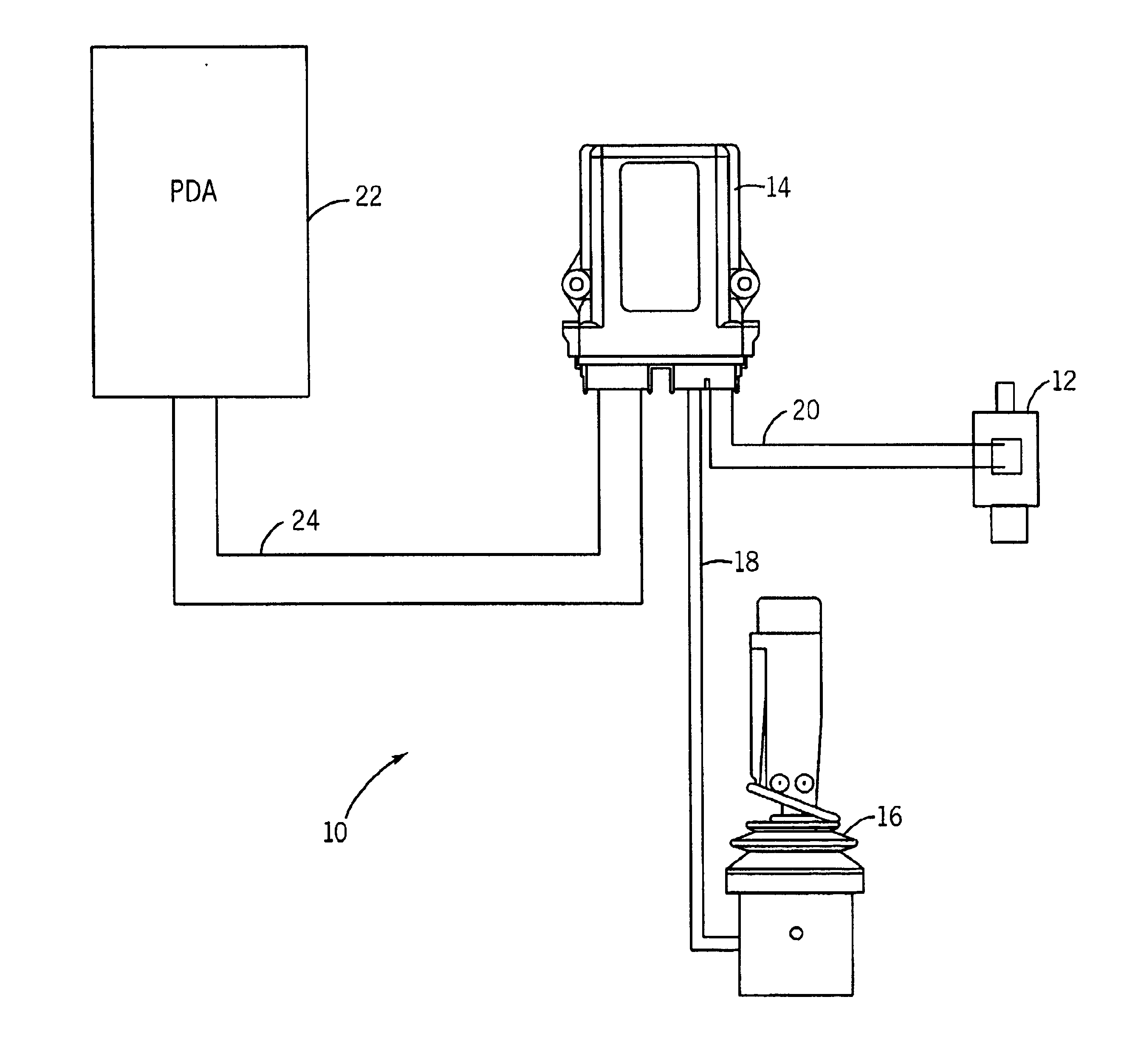
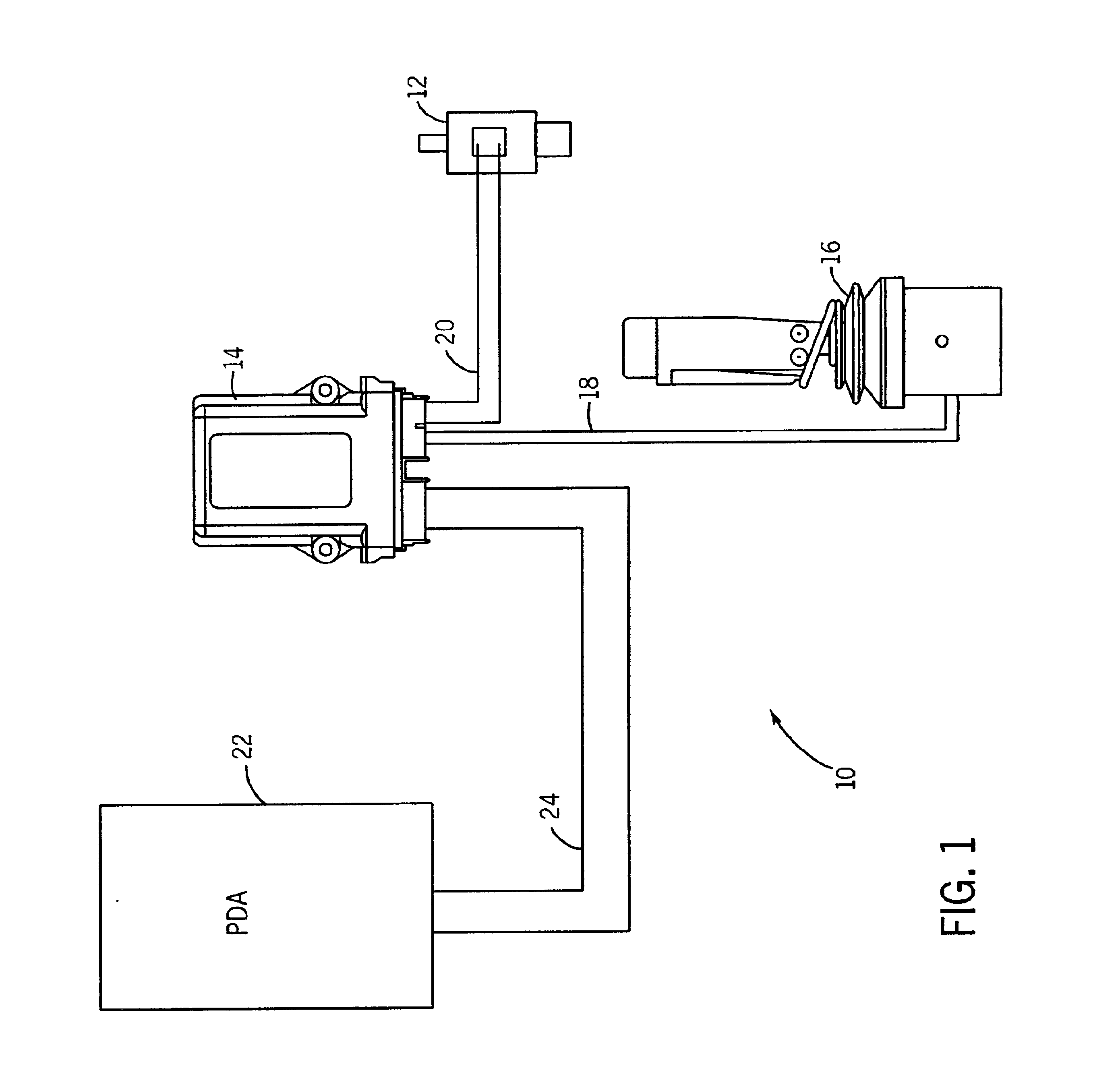
[0027]FIG. 1 is a schematic block diagram illustrating an output device control system in accordance with one aspect of the invention. The output device control system is identified generally by the numeral 10. System 10 is used to control output device or output control device 12. Output control device may be any desired device, such as is used in manufacturing processes, construction processes or other device that is desired to be actuated as part of an overall physical process. Control output device 12 may include, for example, hydraul...


PUM


Abstract

A system and software for controlling output devices used in association with machinery is disclosed. The system includes a control module which may be connected to a personal digital assistant (PDA), personal pocket PC, personal computer, organizer, cell phone, or other data storage device. The data storage device has programmed within it particularized manufacturer information for various input devices and output devices available on the market. The system allows an operator to select a particular manufacturer, as well as product information, including product model number and operating parameters. The machine can then be calibrated such that the input device being used, as well as the output device manufacturer information, is used to dynamically adjust, monitor or perform diagnostics on the machine. The system allows for on-site calibration of the machine controllers. The invention contemplates the use of any output device used with the operation of the machine or any input device used to input information or operation instructions to the machine. The software may be programmed into any personal electronic device or may be connected to a driver or controller associated with the machine to be regulated.

Description

RELATED APPLICATION[0001]This application claims priority of U.S. Provisional Patent Application No. 60 / 329,039 filed on Oct. 12, 2001.BACKGROUND OF THE INVENTION[0002]The invention relates generally to control systems used in industrial applications. More particularly, the invention relates to control systems that can store programs and maintain preset specifications for control of input and output devices used in a particular industrial application.[0003]In industrial settings, including manufacturing and construction, it is common to utilize control systems that regulate such items as valves, motors, hydraulics, circuits, etc. These items, referred to as output devices are operated by, for example, a worker using an input device such as a joystick, such as is described in U.S. Pat. No. 5,293,900 and U.S. Pat. No. 5,389,752, the teachings of which are herein incorporated by reference. Other devices may include potentiometers, sensors, etc. Usually, a driver / controller is used to c...

Claims


Application Information

Patent Timeline
IPC IPC(8): G05B23/02
CPCG05B19/042
Inventor KARBASSI, HASSAN
Owner KAR TECH
Why Eureka
Try Eureka