Device for manufacturing glass gobs

a technology of glass gobs and glass shells, which is applied in the direction of glass making apparatus, glass shaping apparatus, instruments, etc., can solve the problems of minimal stability of the membrane material, achieve convenient high gas throughput, optimize the gas cushion, and reduce the effect of pore siz

Inactive Publication Date: 2005-06-21
SCHOTT AG
View PDF19 Cites 4 Cited by
  • Summary
  • Abstract
  • Description
  • Claims
  • Application Information

AI Technical Summary

Benefits of technology

[0012]A further advantage of the invention is as follows: A membrane material which has smaller pores than previously can be used due to the increase according to the present invention in stability of the membrane body. Conveniently high gas throughputs can be achieved, again allowing the gas cushion to be built up to be optimized. If membrane bodies were used instead, which are designed according to the prior art, they would have to have minimal thickness and be operated at high pressures. This leads to extreme material stresses and thus to the risk of breakage.
[0013]In the case of the design according to the present invention, however, conveniently and without risk of breakage, high gas throughputs can be achieved, with which the gas cushion to be built up can again be optimized.
[0014]Again on account of the increased stability, there is relatively free choice of the membrane material. Porous graphite is also considered as membrane material. In the case of small gobs of minimal weight, graphite of moderate quality suffices.
[0016]In the case of known, self-contained membranes there is frequently flattening of the supporting, softened glass gobs on their underside in their central region. This can lead to a convex contour forming. The reason for this is that the levitation gas of the gas cushion exits from the entire membrane surface, but it can leave the interstice between the gas outlet surface of the membrane and the glass gob only at the edge of the membrane. This creates gas congestion under the supporting glass gob in the abovementioned central region, which leads to the desired flattening or denting.
[0017]This phenomenon can be counteracted by corresponding dimensioning and configuring of the channels according to the present invention. Outlet channels can be provided which cause the gas stream escaping in the central region to be reduced. In the interests of achieving optimum results, an outlet channel, which leads away from the gas outlet surface, can even be provided in the central region. Such a channel can be provided with control systems, or can even be connected to a subpressure source.

Problems solved by technology

A particular disadvantage is that the membrane material exhibits minimal stability only.

Method used


Image

  • Device for manufacturing glass gobs
  • Device for manufacturing glass gobs
  • Device for manufacturing glass gobs

Examples


Embodiment Construction

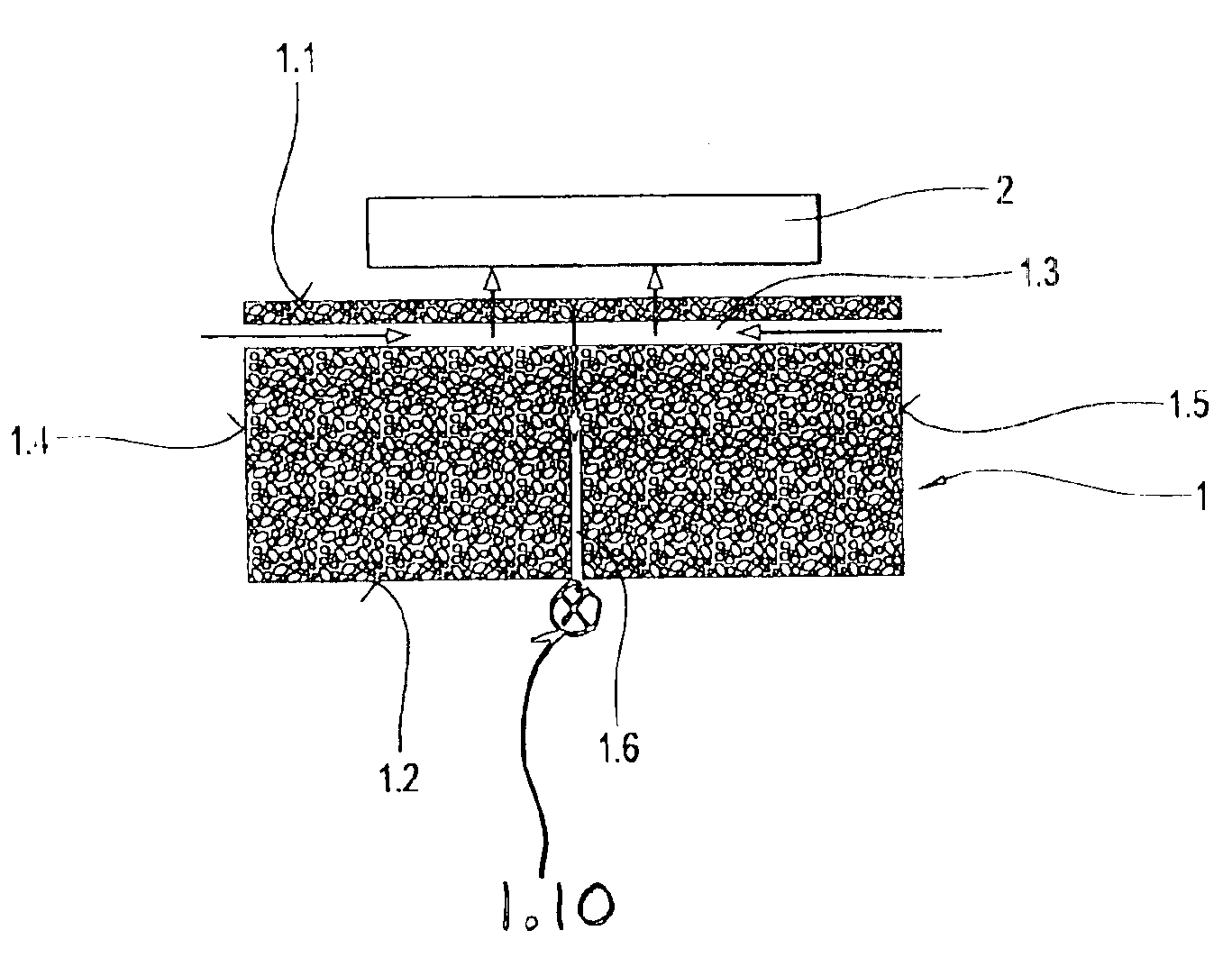
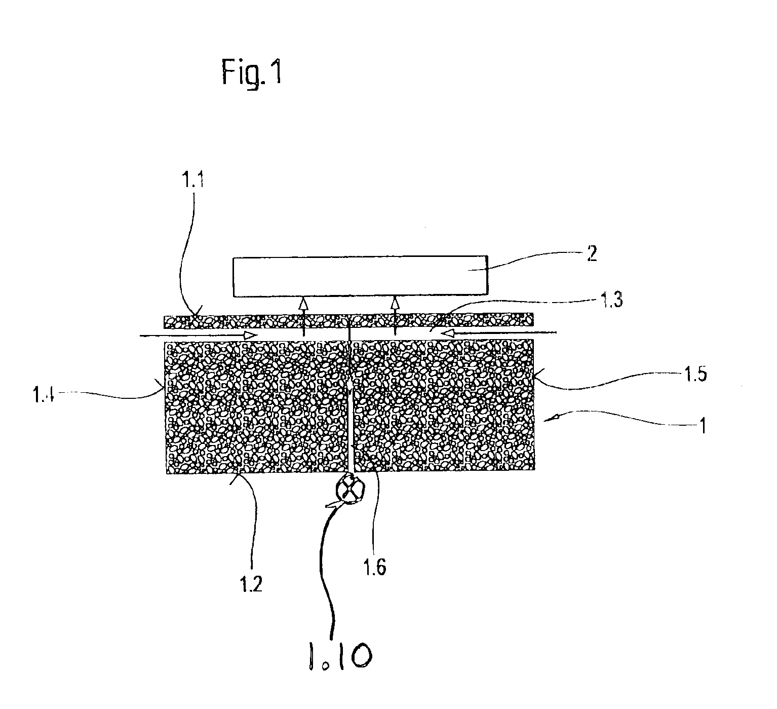
[0023]The membrane body 1 illustrated in FIG. 1 helps form an air cushion to support a glass body 2.

[0024]The membrane body 1 is considerably thick, as compared to known membrane discs. As is evident, in the present case the thickness is approximately half its length. It would also be possible to make the membrane body somewhat thinner, so that the ratio of thickness to length is approximately 1:4, or to make the thickness even greater than illustrated here, so that the ratio of thickness to length is approximately 1:1.

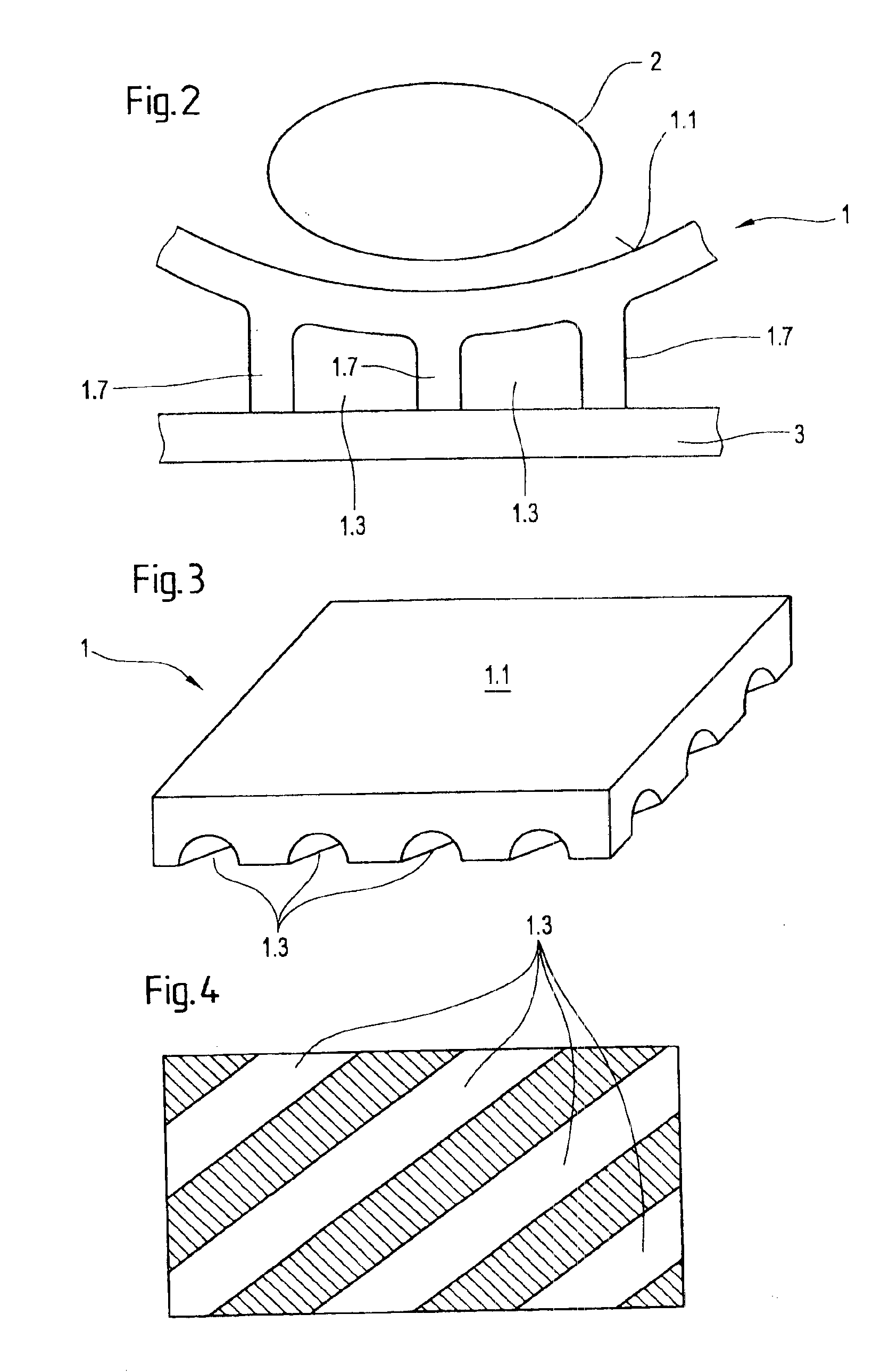
[0025]The membrane body 1 exhibits an upper surface 1.1 and a lower surface 1.2. The upper surface 1.1 is called gas outlet surface hereinbelow.

[0026]There is also a channel 1.3 which runs through the membrane body 1. In the present case channel 1.3 runs parallel to the gas outlet surface 1.1. It could also run inclined at a certain angle to the gas outlet surface 1.1. It is important that it runs at a certain distance from the gas outlet surface 1.1. This distance ca...


PUM

PropertyMeasurementUnit
distanceaaaaaaaaaa
acute angleaaaaaaaaaa
diameteraaaaaaaaaa

Abstract

A device for manufacturing glass gobs includes a membrane body of a porous gas transmitting material. Channels for introducing compressed gas into the membrane body extend through the membrane body material and are spaced at a distance from the gas outlet surface of the membrane body. The channels run parallel to or are at an acute angle to the outlet surface. In an alternate embodiment, the channels are open channels at the opposite surface from the outlet surface.

Description

BACKGROUND OF THE INVENTION[0001]The present invention relates to a device for manufacturing so-called gobs from glass. Such gobs serve as intermediate products for optical articles, such as lenses.[0002]U.S. Pat. No. 5,762,673 describes a device, in which glass balls defined by dropping are produced from a molten mass of glass. The glass balls are kept in suspension in a gas stream while at the same time being brought to a specific temperature and a specific viscosity. In a further procedural step the glass gobs are subjected to a pressing procedure, followed by further processing steps.[0003]The present invention focuses on that phase of the known process, in which the glass gob is kept in suspension for a certain period by means of a gas stream. During this time the glass balls or gobs can cool off, be heated and / or kept at a certain temperature. The associated device comprises a membrane of an open-pored material as an essential element. The membrane may be discoid. The disc can...

Claims


Application Information

Patent Timeline
Patent Type & Authority Patents(United States)
IPC IPC(8): C03B19/00C03B40/00C03B19/02C03B40/04C03B7/14G02B3/00C03B11/00
CPCC03B40/04C03B19/02
Inventor LANGSDORF, ANDREASKUNERT, CHRISTIAN
Owner SCHOTT AG
Why Eureka
Try Eureka