Heated volatile dispensing device with dye-based use-up indicator

a technology of dye-based use-up indicator and heating volatile, which is applied in the field of indicators, can solve the problems of affecting the heating performance of the heater, affecting the heating effect of the heater, and changing the appearance of the substrate, etc., and achieves the effect of small pores and high density polyethylen

Inactive Publication Date: 2009-04-28
SC JOHNSON & SON INC
View PDF20 Cites 2 Cited by
  • Summary
  • Abstract
  • Description
  • Claims
  • Application Information

AI Technical Summary

Benefits of technology

[0025]The dye could be encapsulated (a “covering”) prior to use with a meltable wax or plastic (e.g. ethylene vinyl acetate or polyethylene). Alternatively, it could be stored prior to use in separate cavities under substrate portions having pores that are initially too tiny to permit migration to a visible surface at room temperature. Heating of the substrate can expand the pores and thus permit such migration. Each dye could be stored in a different pore / substrate configuration. In this regard, a nylon 6.6 substrate with larger pores could permit one speed of migration of one dye, and a high density polyethylene substrate with smaller pores could permit a second dye to migrate more slowly.
[0035]The present invention thus provides an automatic means of indicating to a consumer the extent to which a consumable portion of air treatment devices have been used up. The substrates of the present invention are inexpensive to produce, reliable, and conceptually straightforward insofar as a consumer's ability to readily understand how they operate. They help avoid waste due to the premature disposal of such consumables even when they still have considerable useful life, and they help reduce consumer dissatisfaction which can be caused by use of a consumable after its effective life is over.

Problems solved by technology

Further, that type of reservoir system may have certain other disadvantages besides size (e.g. cost).
However, the heating of such a substrate does not typically significantly change the appearance of the substrate, particularly when the substrate is a solid rather than a gel.
Even where only a single type of heater is to be used with a particular type of substrate, heater performance may be inconsistent over time.
While estimated averaging of useful life can provide rough guidance regarding useful life, that estimate will not be exact in most cases.
This reduces the risk that there will be significant use of the product after the product has become ineffective, albeit at the cost of a somewhat higher level of waste due to disposing of some product which still has some useful life.
Even where information is provided by the manufacturer regarding expected useful life, some consumers will not learn of, or alternatively not apply, that information.
Rather, they will assume what an appropriate useful life is or should be, and thus in some cases prematurely throw away the product, and in others use it after its effective life is over.
Further, even where the consumer is initially aware of the appropriate assumption for a usage life, they may forget about the need to replace the product until well after the product has become ineffective.
However, systems of this type are difficult to reliably apply in a heated environment, particularly where the exact heat conditions that the product will be exposed to is not controllable or predictable.
However, these devices typically require consumer intervention to initiate the dye migration, and sometimes require complex structures to control use of the dye.
They thereby unnecessarily increase the cost of the indicator and may also reduce the likelihood of consumer acceptance, particularly where the manner of using the product is not conceptually straightforward.

Method used


Image

  • Heated volatile dispensing device with dye-based use-up indicator
  • Heated volatile dispensing device with dye-based use-up indicator
  • Heated volatile dispensing device with dye-based use-up indicator

Examples


Embodiment Construction

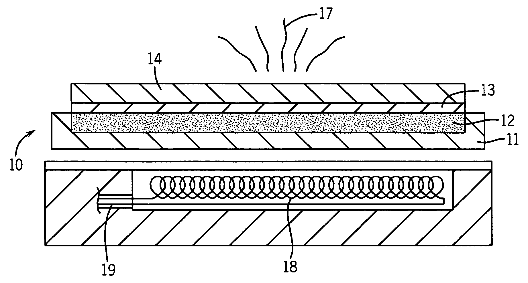
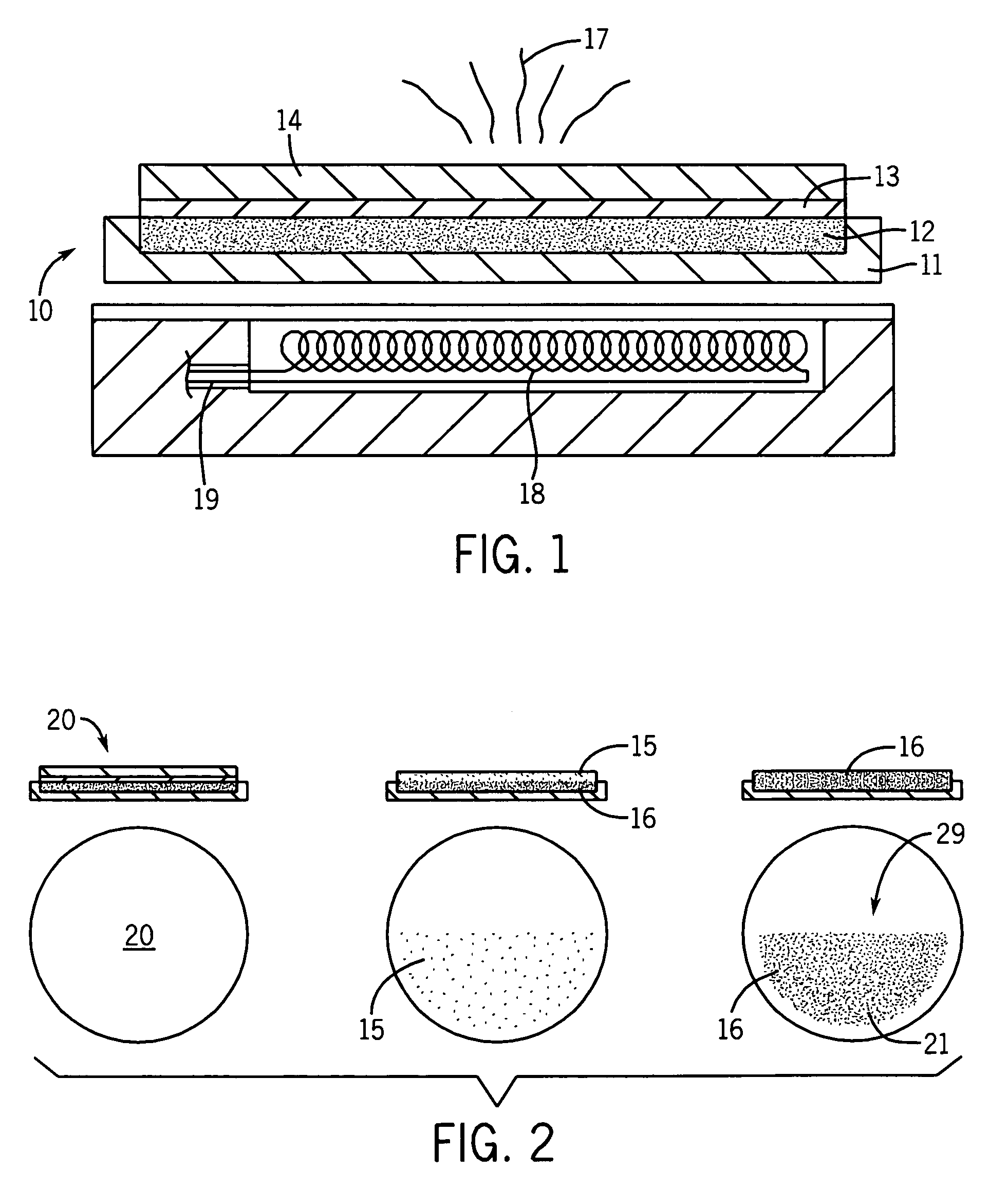
[0043]Referring first to FIGS. 1 and 2, there is shown an air treatment device 10 which has a substrate with a base 11, a cavity 12 filled with a mix of multiple migrate able dyes 15 / 16, a meltable wax covering 13, and a porous substrate layer 14. The base 11 is semi-circular cup-shaped, heat resistant, and impermeable to the dyes. The dye cavity 12 is similarly semi-circular and aligned with both the base 11 and the semi-circular viewing position 29 at the top of the substrate layer 14. The substrate layer 14 is circular in top view. The covering 13 is preferably in the form of a semi-circular top.

[0044]The porous substrate layer 14 is preferably pre-impregnated with an insect control repellent 17 which is dispensed to the air as the substrate layer 14 is heated. An electrical heater 18 heats the substrate layer 14 and is powered by a conventional electrical connection 19. When the heater 18 is turned on, one of the effects is to melt the wax of the covering 13. Upon engaging the h...


PUM


Abstract

Heated volatile dispensers are disclosed that are provided with automated dye-based use-up indicators. Multiple migrateable dyes of different colors are positioned adjacent a porous substrate. Heating of the substrate, such as a slab impregnated with an insect repellent, both causes the impregnated chemical to dispense from the slab and the indicator dyes to migrate to one or more visible positions. One dye migrates to a visible position faster than a dye of a different color. Further heating may cause one or both dyes to change color at a visible position. The dye movement imparts information about the degree of use-up of the impregnating chemical.

Description

CROSS-REFERENCE TO RELATED APPLICATIONS[0001]Not applicable.STATEMENT REGARDING FEDERALLY SPONSORED RESEARCH / DEVELOPMENT[0002]Not applicable.BACKGROUND OF THE INVENTION[0003]The present invention relates to indicators that provide information to consumers about the extent of use of consumable air-treatment products. More specifically, it relates to air treatment dispensing devices where a heater causes dispensing of an air treatment chemical and also initiates a use-up cue system that is in the form of a multiple dye indicator.[0004]A variety of prior art devices are known that use heat to dispense air treatment chemicals. For example, it is known that a porous pad, wick, or other substrate can be impregnated or coated with a volatilizable air treatment chemical. When heat is applied to the substrate, the air treatment chemical is dispensed into the air.[0005]In some of these devices a portion of the substrate is dipped into an associated reservoir of the air treatment chemical (typ...

Claims


Application Information

Patent Timeline
Patent Type & Authority Patents(United States)
IPC IPC(8): A62B7/08A24F25/00
CPCA01M1/2077A61L9/02A61L9/03G01N31/229G04F1/06B60H3/00G04F1/00A01M1/20G01N31/22
Inventor ADAIR, JOEL E.DAVIS, BRIAN T.ANANTH, GOPAL P.VARANASI, PADMA PRABODH
Owner SC JOHNSON & SON INC
Why Eureka
Try Eureka