Injection quantity control device of diesel engine

a technology of quantity control and diesel engine, which is applied in the direction of electrical control, process and machine control, instruments, etc., can solve the problems of inability to directly measure the actual injection quantity of diesel engine while the vehicle is traveling, inability to increase the cost, and the need for additional devices, etc., to achieve accurate calculation

Active Publication Date: 2005-06-21
DENSO CORP
View PDF7 Cites 50 Cited by
  • Summary
  • Abstract
  • Description
  • Claims
  • Application Information

AI Technical Summary

Benefits of technology

[0011]It is therefore an object of the present invention to provide a fuel injection control device of a diesel engine capable of accurately performing learning of an injection quantity without an increase of a cost due to additional devices such as sensors.

Problems solved by technology

However, it is difficult to directly measure the actual injection quantity while a vehicle is traveling.
Therefore, no additional device is required and an increase in the cost can be inhibited.
However, in the method disclosed in Unexamined Japanese Patent Application Publication No.
Thus, the additional devices are required and the cost is increased.
Therefore, it is difficult to accurately perform the learning of the injection quantity.
Therefore, the actual injection quantity cannot be sensed accurately by merely monitoring the engine rotation speed.

Method used


Image

  • Injection quantity control device of diesel engine
  • Injection quantity control device of diesel engine
  • Injection quantity control device of diesel engine

Examples


first embodiment

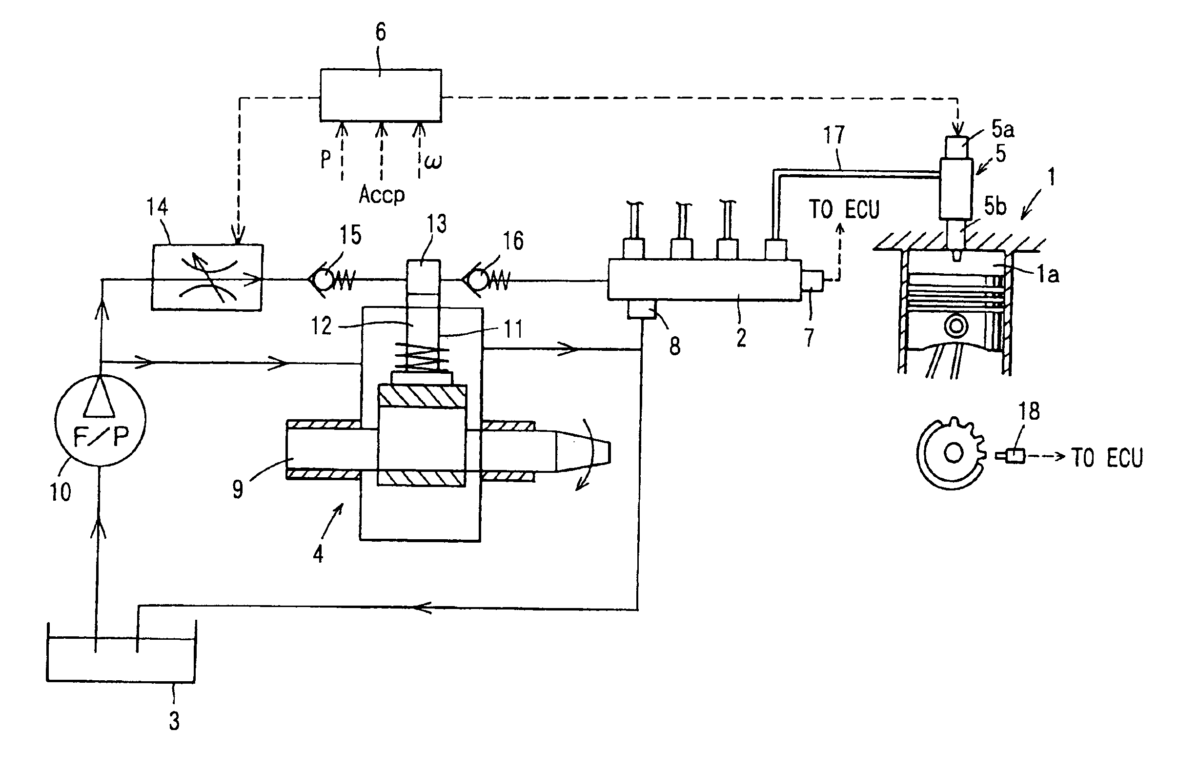
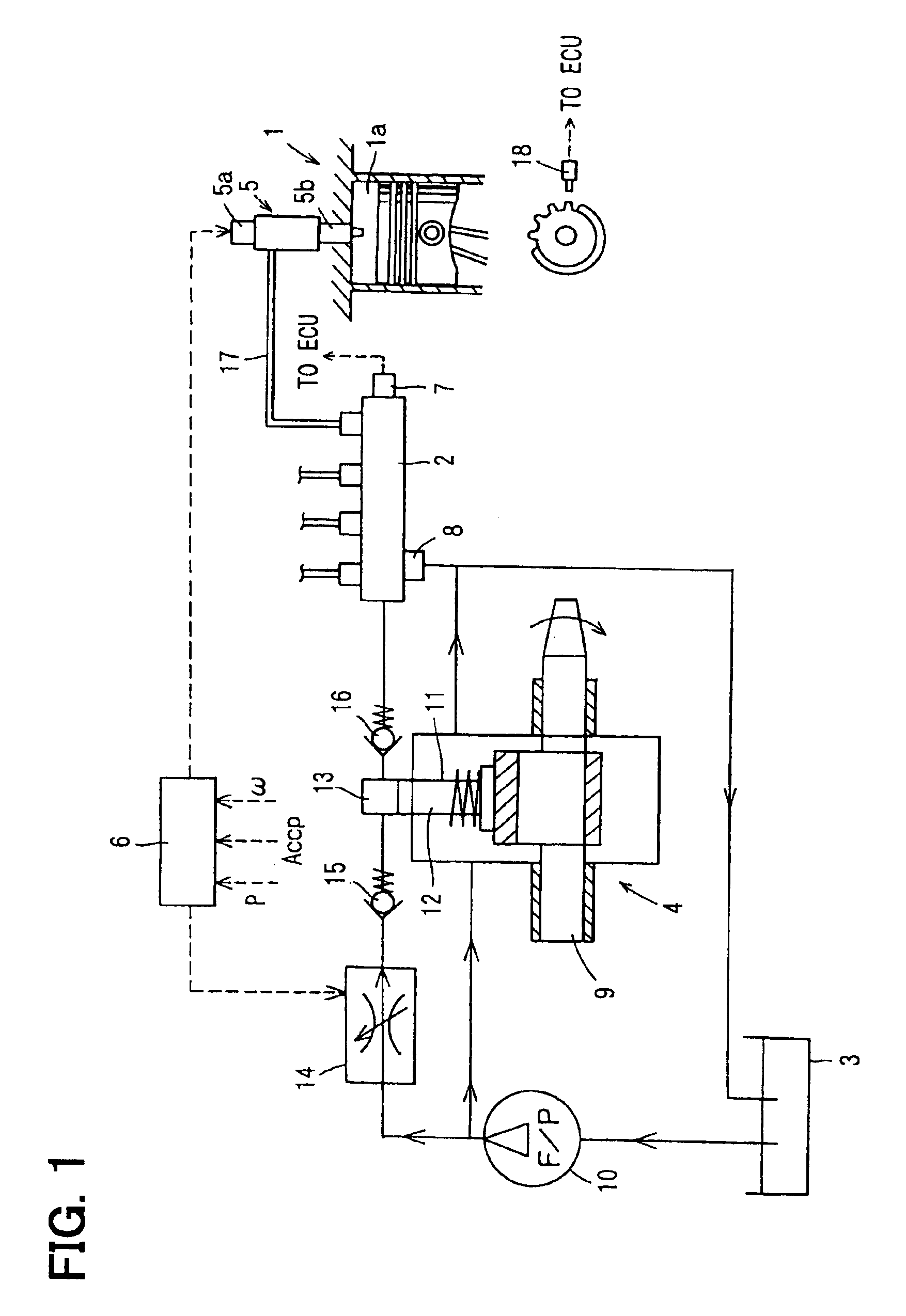
[0023]Referring to FIG. 1, a fuel injection system of a diesel engine according to a first embodiment of the present invention is illustrated.

[0024]The fuel injection system shown in FIG. 1 is applied to a four-cylinder diesel engine (an engine) 1, for instance. The fuel injection system includes a common rail 2 for accumulating high-pressure fuel, a fuel supply pump 4 for pressurizing the fuel drawn from a fuel tank 3 and for supplying the fuel into the common rail 2, injectors 5 for injecting the high-pressure fuel, which is supplied from the common rail 2, into cylinders (combustion chambers 1a), and an electronic control unit (an ECU) 6 for electronically controlling the system.

[0025]The ECU 6 sets a target rail pressure of the common rail 2. The common rail 2 accumulates the high-pressure fuel supplied from the fuel supply pump 4 to the target rail pressure. A pressure sensor 7 and a pressure limiter 8 are attached to the common rail 2. The pressure sensor 7 senses a pressure o...

second embodiment

[0054]Next, a method of estimating the actual injection quantity QA performed by the ECU 6 according to a second embodiment of the present invention will be explained based on FIG. 7.

[0055]In the second embodiment, the average δx of the rotation speed increases δ caused by the single-shot injection is calculated in Step S33 of the first embodiment, and then, the actual injection quantity QA is estimated based on a map shown in FIG. 7.

[0056]The map shown in FIG. 7 stores values for preliminarily matching the average δx of the rotation speed increases δ with the engine rotation speed ω0, which is sensed when the single-shot injection is performed, for each injection quantity. Therefore, the actual injection quantity QA can be calculated from the map in accordance with the average δx of the rotation speed increases δ and the engine rotation speed ω0 at the time when the learning injection is performed.

Modification

[0057]In the first embodiment, the learning of the injection quantity of ...


PUM


Abstract

A fuel injection control device of a diesel engine performs a learning injection during a no-injection period, in which a command injection quantity is zero or under. A difference between a variation in the engine rotation speed in the case where the learning injection is performed and a variation in the engine rotation speed in the case where the learning injection is not performed is calculated as a rotation speed increase. A torque proportional quantity is calculated by multiplying the rotation speed increase by the engine rotation speed at the time when the learning injection is performed. An injection correction value is calculated from a deviation between the actual injection quantity, which is estimated from the torque proportional quantity, and the command injection quantity. The command injection quantity is corrected based on the injection correction value.

Description

CROSS REFERENCE TO RELATED APPLICATIONS[0001]This application is based on and incorporates herein by reference Japanese Patent Applications No. 2003-185633 filed on Jun. 27, 2003 and No. 2003-419915 filed on Dec. 17, 2003.BACKGROUND OF THE INVENTION[0002]1. Field of the Invention[0003]The present invention relates to a fuel injection control device, which performs learning of an injection quantity of a diesel engine.[0004]2. Description of Related Art[0005]A pilot injection for injecting a small amount of fuel before a main injection is performed in order to reduce combustion noise and to inhibit generation of nitrogen oxides in a diesel engine. Since a command value of an injection quantity of the pilot injection is small, accuracy of the small-amount injection should be improved in order to sufficiently exert the effect of the pilot injection of reducing the combustion noise and of inhibiting the nitrogen oxides. Therefore, learning should be preferably performed in the software f...

Claims


Application Information

Patent Timeline
Patent Type & Authority Patents(United States)
IPC IPC(8): F02D41/14F02D41/12F02D41/00F02D41/40F02D41/24F02D45/00F02D41/38F02D43/00
CPCF02D41/123F02D41/1497F02D41/2467F02D41/403F02D41/2438Y02T10/44Y02T10/40
Inventor ASANO, MASAHIRONARAHARA, YOSHIHIROTAKEMOTO, EIJI
Owner DENSO CORP
Why Eureka
Try Eureka