Storage tank for hot water systems

a technology for storage tanks and hot water systems, applied in the direction of heating types, instruments, domestic cooling devices, etc., to achieve the effect of reducing heat transfer

Inactive Publication Date: 2005-06-21
CARRIER CORP
View PDF23 Cites 26 Cited by
  • Summary
  • Abstract
  • Description
  • Claims
  • Application Information

AI Technical Summary

Benefits of technology

[0006]A storage tank stores the water that exchanges heat with the refrigerant in the heat rejecting heat exchanger. A mechanical interface plate positioned between a hot reservoir and a cold reservoir in the storage tank reduces heat transfer between the water in the hot reservoir and the cold reservoir. As the cold water in the cold reservoir is more dense than the hot water in the hot reservoir, it is below the hot reservoir. The mechanical interface plate is designed to have an effective density between the hot and cold water densities, enabling the mechanical interface plate to float between the two reservoirs.

Problems solved by technology

The amount of hot water in the storage tank varies at any given time as the hot water generation capacity typically does not match the load demands of the system.

Method used


Image

  • Storage tank for hot water systems
  • Storage tank for hot water systems
  • Storage tank for hot water systems

Examples


Embodiment Construction

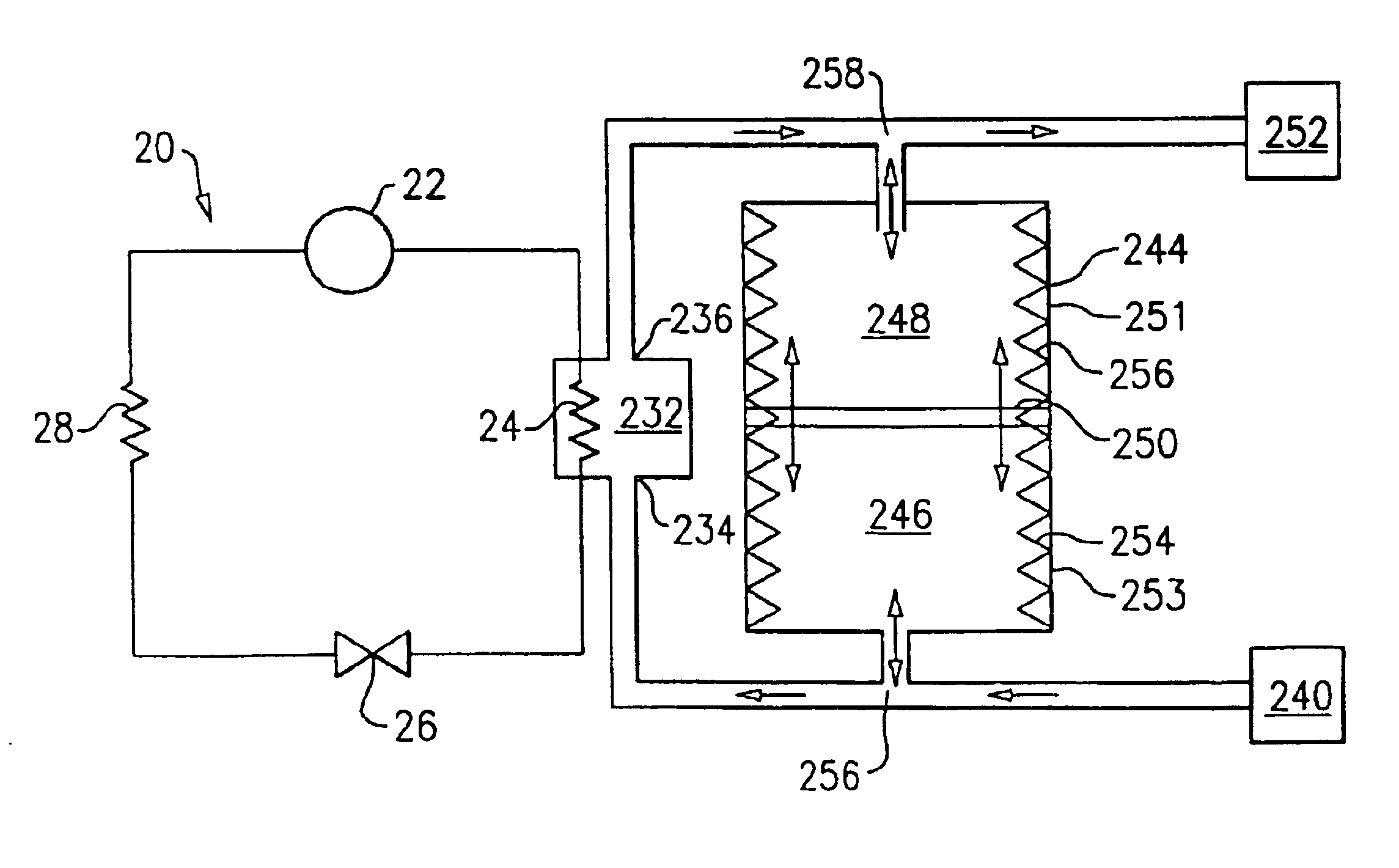
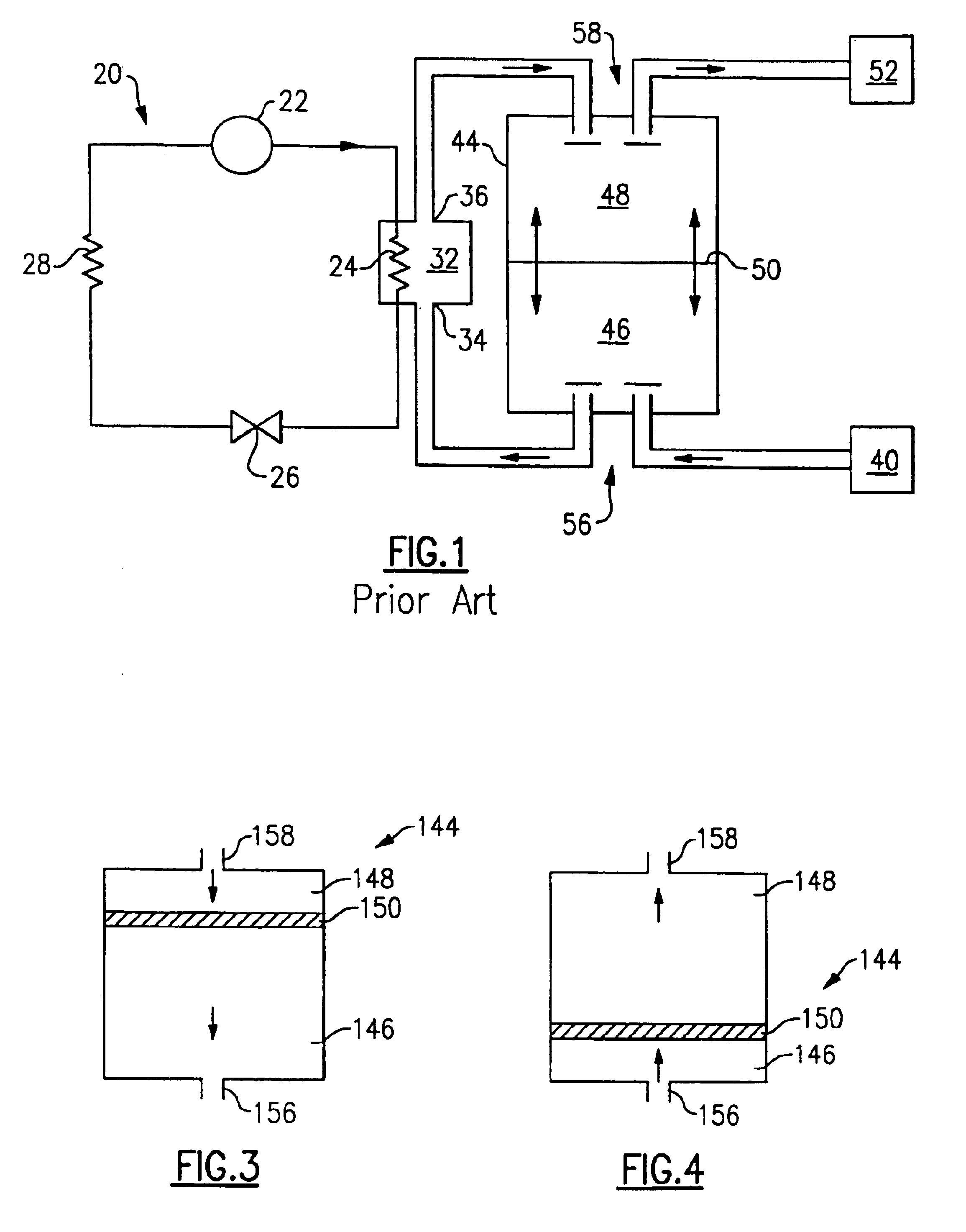
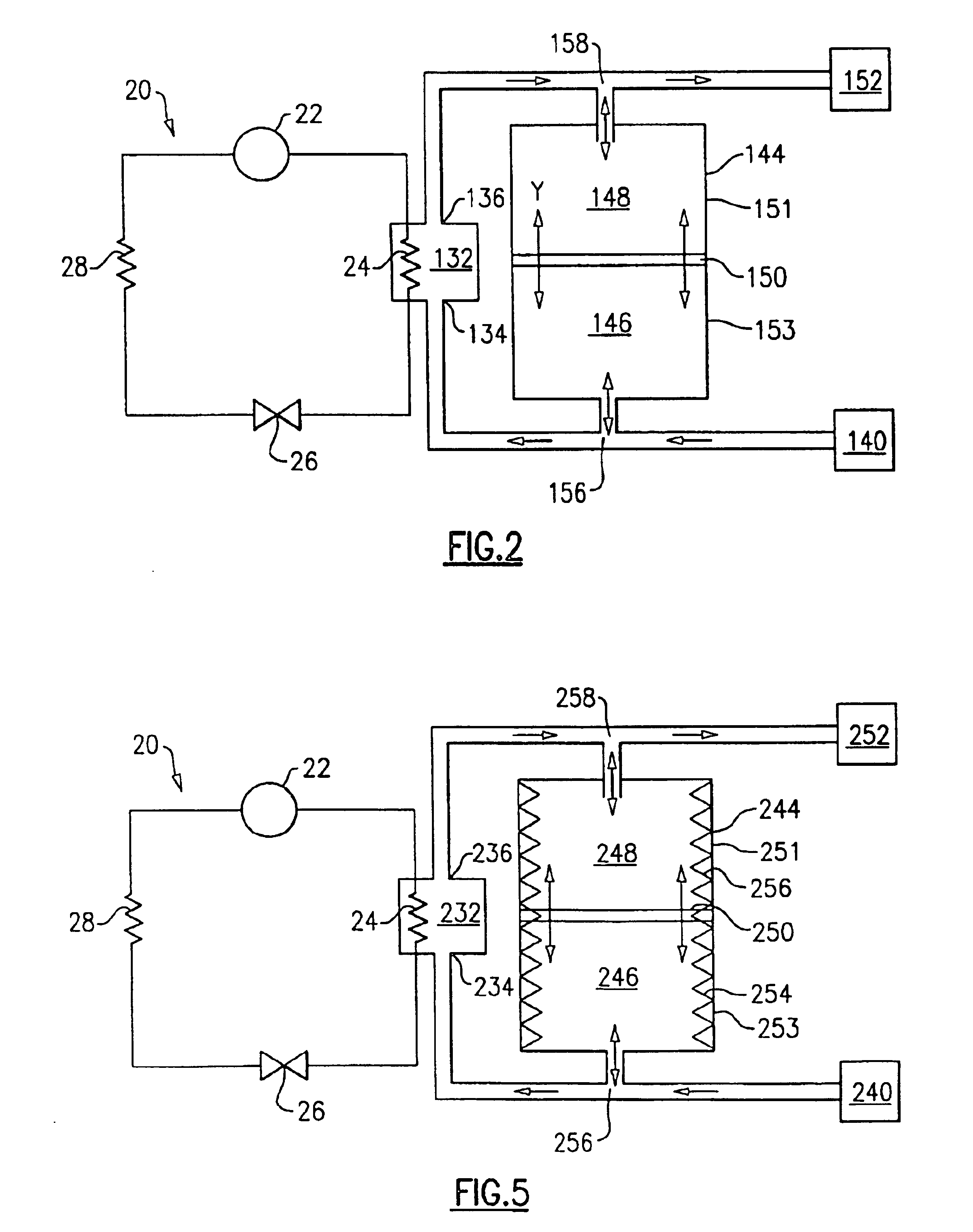
[0017]FIG. 1 illustrates a prior art heat pump water system 20 including a compressor 22, a heat rejecting heat exchanger 24, an expansion device 26, and a heat accepting heat exchanger 28. Refrigerant circulates though the closed circuit system 20.

[0018]The refrigerant exits the compressor 22 at high pressure and enthalpy and flows through the heat rejecting heat exchanger 24. In the heat rejecting heat exchanger 24, the refrigerant loses heat, exiting the heat rejecting heat exchanger 24 at low enthalpy and high pressure. A fluid medium, such as water, flows through a heat sink 32 and exchanges heat with the refrigerant passing through the heat rejecting heat exchanger 24. After exchanging heat with the refrigerant, the heated water exits through the heat sink outlet 36. The refrigerant then passes through the expansion device 26, and the pressure drops. After expansion, the refrigerant flows through the heat accepting heat exchanger 28 and exits at a high enthalpy and low pressur...


PUM


Abstract

A heat pump system includes a compressor, a heat rejecting heat exchanger, an expansion device, and a heat accepting heat exchanger. A storage tank stores the water that cools the refrigerant in the heat rejecting heat exchanger. A mechanical interface plate positioned between a hot water reservoir and a cold water reservoir in the storage tank reduces heat transfer between the hot water and the cold water. During a water heating mode, cold water from the cold reservoir flows into the heat sink to cool the refrigerant in the heat rejecting heat exchanger. As the water exchanges heat with the refrigerant, the water is heated in the heat sink, exits the heat sink, and flows into the hot reservoir of the storage tank. During a water discharge mode, the hot water in the hot reservoir is removed from the storage tank and flows into a hot water discharge. Cold water from a water source flows into the cold reservoir of the storage tank to refill the storage tank.

Description

BACKGROUND OF THE INVENTION[0001]The present invention relates generally to a storage tank for a hot water system that includes a mechanical insulator for the separation of the hot layer and the cold layer.[0002]Hot water systems commonly include a storage tank that stores the fluid, such as water, that cools the refrigerant in the heat rejecting heat exchanger. By employing a storage tank, the size, cost, and cycling of the hot water generation component can be reduced. In a heat pump system, hot water is generated outside of the storage tank. Heat pump system efficiency is directly related to the inlet temperature of the water in the heat sink which exchanges heat with the refrigerant. As the inlet temperature of the fluid into the heat sink decreases, system efficiency increases.[0003]By flowing water into the storage tank slowly, a hot layer and cold layer can be formed in the storage tank which is separated by a thermal interface layer. The amount of hot water in the storage ta...

Claims


Application Information

Patent Timeline
Patent Type & Authority Patents(United States)
IPC IPC(8): F24D17/02F28D20/00
CPCF24D17/02F28D20/0039Y02E60/142F28D2020/0095F28D2020/0091Y02E60/14
Inventor SIENEL, TOBIAS H.
Owner CARRIER CORP
Why Eureka
Try Eureka