Apparatus for securing a yoke to a tube using magnetic pulse welding techniques

a technology of magnetic pulse and yoke, which is applied in the direction of welding apparatus, non-electric welding apparatus, manufacturing tools, etc., can solve the problems of undesirable distortion and weaknesses, inability to perform conventional welding techniques with pressure, and inability to achieve the effect of preventing deformation of the opposed yoke arms and reducing the amount of undesirable distortion

Inactive Publication Date: 2005-06-21
TORQUE TRACTION TECH INC
View PDF36 Cites 9 Cited by
  • Summary
  • Abstract
  • Description
  • Claims
  • Application Information

AI Technical Summary

Benefits of technology

[0008]This invention relates to an improved apparatus that minimizes the amount of undesirable distortions that can result in a yoke or similar end fitting when a driveshaft tube is secured thereto by a magnetic pulse welding operation. The support apparatus includes a lower jaw, an upper jaw, and a support pin extending therebetween. During the magnetic pulse welding operation, the lower and upper jaws of the support apparatus engage the opposed yoke arms, and the support pin extends through respective openings formed through the opposed yoke arms. The support apparatus can also include a counter die that is disposed between the lower jaw and the upper jaw and has an arcuate recess formed therein that receives the outer portions of the opposed yoke arms therein. Lastly, the support apparatus can further include a pair of positioning rails that engage the body portion of the yoke. As a result, the support apparatus prevents deformation of the opposed yoke arms and absorbs shock waves that can be propagated through the yoke during the magnetic pulse welding operation.

Problems solved by technology

As is well known, conventional welding techniques involve the application of heat to localized areas of two metallic members, which results in a coalescence of the two metallic members.
Such conventional welding techniques may or may not be performed with the application of pressure, and may or may not include the use of a filler metal.
Although conventional welding techniques have functioned satisfactorily in the past, there are some drawbacks to the use thereof in joining the first and second end fittings to the ends of the driveshaft tube.
This application of heat can cause undesirable distortions and weaknesses to be introduced into the metallic components.
Second, while conventional welding techniques are well suited for joining components that are formed from similar metallic materials, it has been found to be somewhat more difficult to adapt them for use in joining components formed from dissimilar metallic materials.
Third, conventional welding techniques are not easily adapted for joining components that have different gauge thicknesses.
This electromagnetic field exerts a very large force on the outer surface of the end portion of the driveshaft tube, causing it to collapse inwardly at a high velocity onto the neck portion of the end fitting.
Unfortunately, it has been found that the high velocity impact of the end portion of the driveshaft tube onto the neck portion of the end fitting during the magnetic pulse welding operation can, in some instances, cause the yoke arms of the end fitting to be permanently deflected relative to one another.
Such deflections of the yoke arms are undesirable because they can result in the misalignment of the respective openings formed therethrough.
When the openings formed through the yoke arms are not precisely aligned, it may be relatively difficult to properly install the remaining portions of the universal joint thereon and to balance the universal joint for rotation.

Method used


Image

  • Apparatus for securing a yoke to a tube using magnetic pulse welding techniques
  • Apparatus for securing a yoke to a tube using magnetic pulse welding techniques
  • Apparatus for securing a yoke to a tube using magnetic pulse welding techniques

Examples


Embodiment Construction

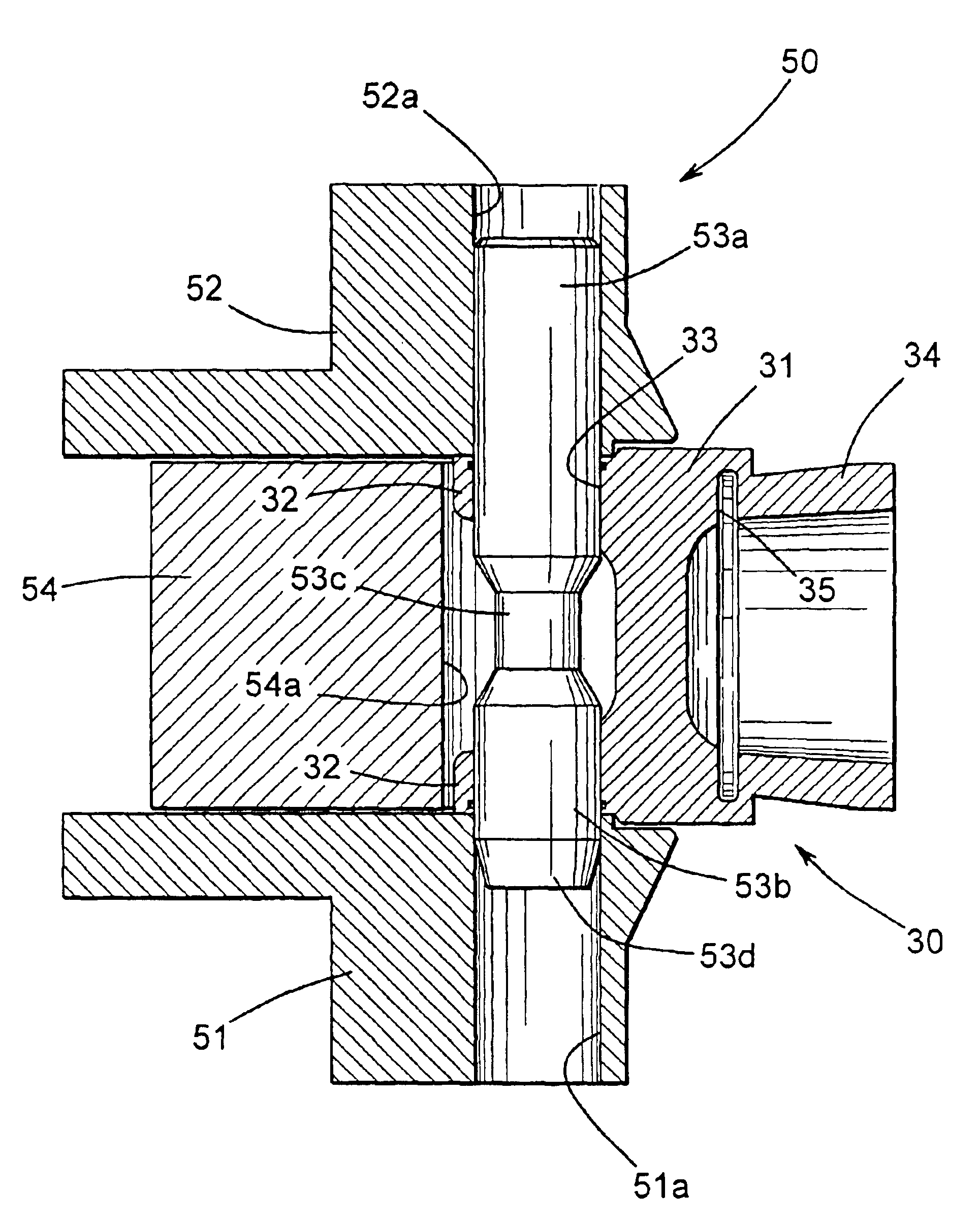
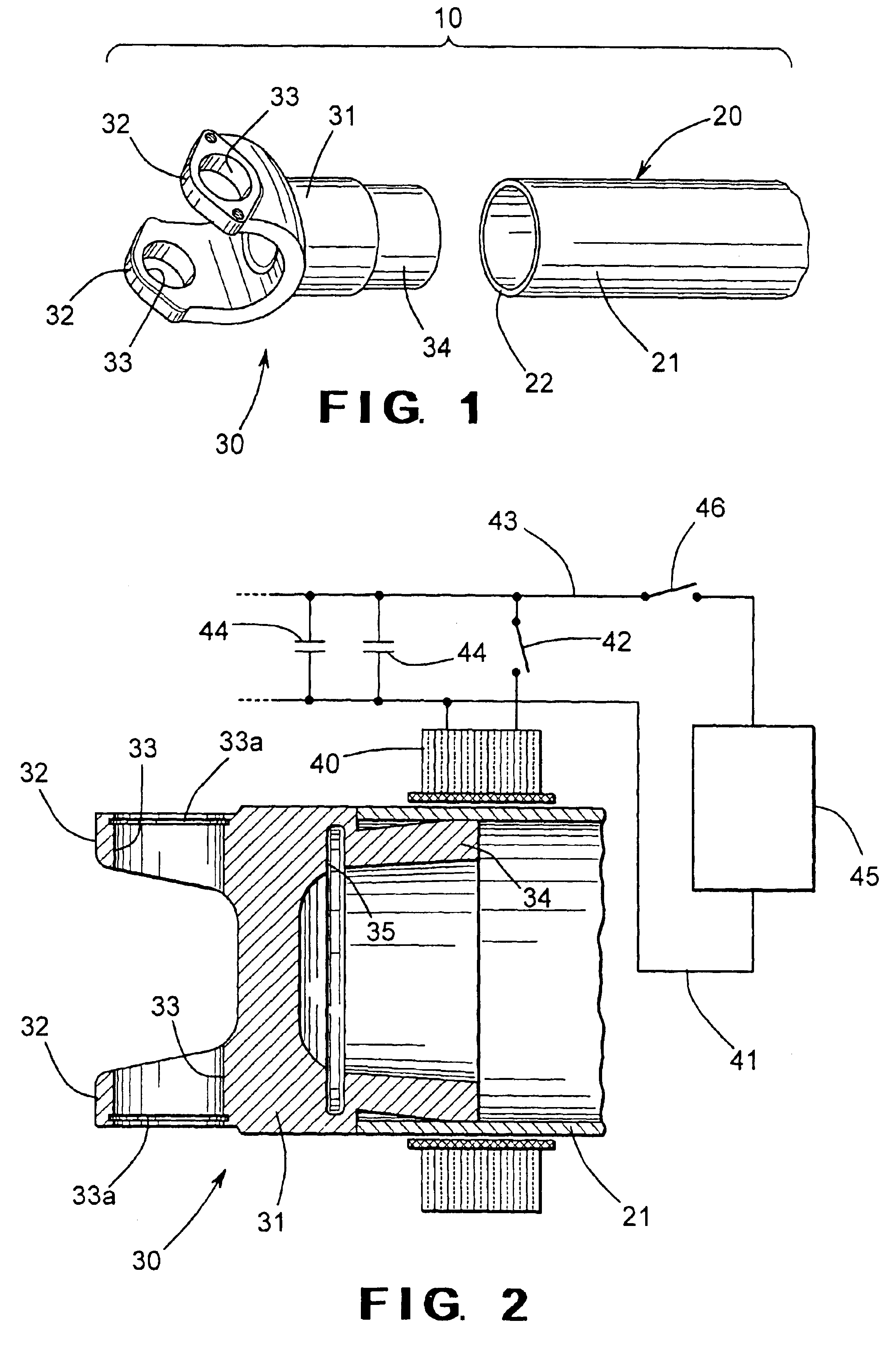
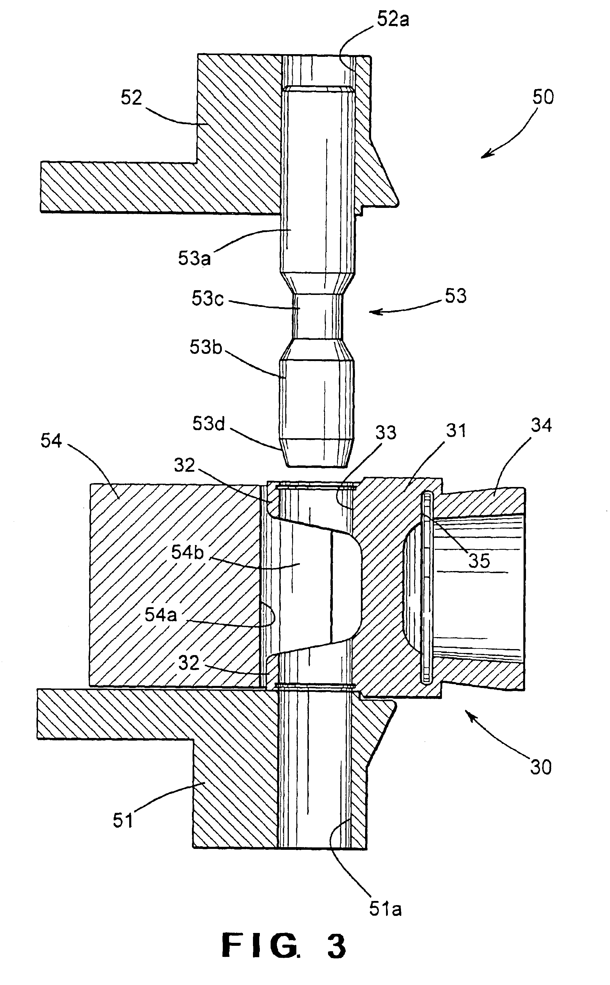
[0015]Referring now to the drawings, there is illustrated in FIGS. 1 and 2 a portion of a vehicular driveshaft assembly 10 that includes a driveshaft tube, indicated generally at 20, and a first embodiment of an end fitting, indicated generally at 30. Although this invention will be described and illustrated in the context of securing an end fitting to a driveshaft tube to form a portion of a vehicular driveshaft assembly, it will be appreciated that the method of this invention can be used to secure any two metallic components together for any desired purpose or application.

[0016]The illustrated driveshaft tube 20 is generally hollow and cylindrical in shape and can be formed from any desired metallic material, such as 6061 T6 aluminum alloy, for example. Preferably, the driveshaft tube 20 has an outer surface that defines a substantially constant outer diameter and an inner surface that defines a substantially constant inner diameter. Thus, the illustrated driveshaft tube 20 has a...


PUM

PropertyMeasurementUnit
dimensionaaaaaaaaaa
rotational poweraaaaaaaaaa
pressureaaaaaaaaaa

Abstract

An apparatus for supporting a workpiece, such as a yoke having a body portion and a pair of opposed yoke arms, during a magnetic pulse welding operation includes a lower jaw, an upper jaw, and a support pin extending therebetween. During the magnetic pulse welding operation, the lower and upper jaws of the support apparatus engage the opposed yoke arms, and the support pin extends through respective openings formed through the opposed yoke arms. The support apparatus can also include a counter die that is disposed between the lower jaw and the upper jaw and has an arcuate recess formed therein that receives the outer portions of the opposed yoke arms therein. Lastly, the support apparatus can further include a pair of positioning rails that engage the body portion of the yoke. As a result, the support apparatus prevents deformation of the opposed yoke arms and absorbs shock waves that can be propagated through the yoke during the magnetic pulse welding operation.

Description

CROSS REFERENCE TO RELATED APPLICATION[0001]This application claims the benefit of U.S. Provisional Application Ser. No. 60 / 361,938, filed Mar. 6, 2002, the disclosure of which is incorporated herein by reference.BACKGROUND OF THE INVENTION[0002]This invention relates in general to the use of magnetic pulse welding techniques to secure two metallic components together, such as a yoke and a driveshaft tube in a vehicular driveshaft assembly. In particular, this invention relates to an improved apparatus that minimizes the amount of undesirable distortions that can result in a yoke or similar end fitting when a driveshaft tube is secured thereto by means of such a magnetic pulse welding operation.[0003]In most land vehicles in use today, a drive train system is provided for transmitting rotational power from an output shaft of an engine / transmission assembly to an input shaft of an axle assembly so as to rotatably drive one or more wheels of the vehicle. To accomplish this, a typical ...

Claims


Application Information

Patent Timeline
Patent Type & Authority Patents(United States)
IPC IPC(8): B23K20/06
CPCB23K20/06
Inventor YABLOCHNIKOV, BORIS A.
Owner TORQUE TRACTION TECH INC
Why Eureka
Try Eureka