Low loss interconnect structure for use in microelectronic circuits

a microelectronic circuit and interconnect technology, applied in the field of microelectronic circuits, can solve the problems of loss within on-die interconnects, which is now becoming a greater concern, and transmission structures with relatively low loss are typically required

Inactive Publication Date: 2005-06-21
INTEL CORP
View PDF39 Cites 21 Cited by
  • Summary
  • Abstract
  • Description
  • Claims
  • Application Information

AI Technical Summary

Problems solved by technology

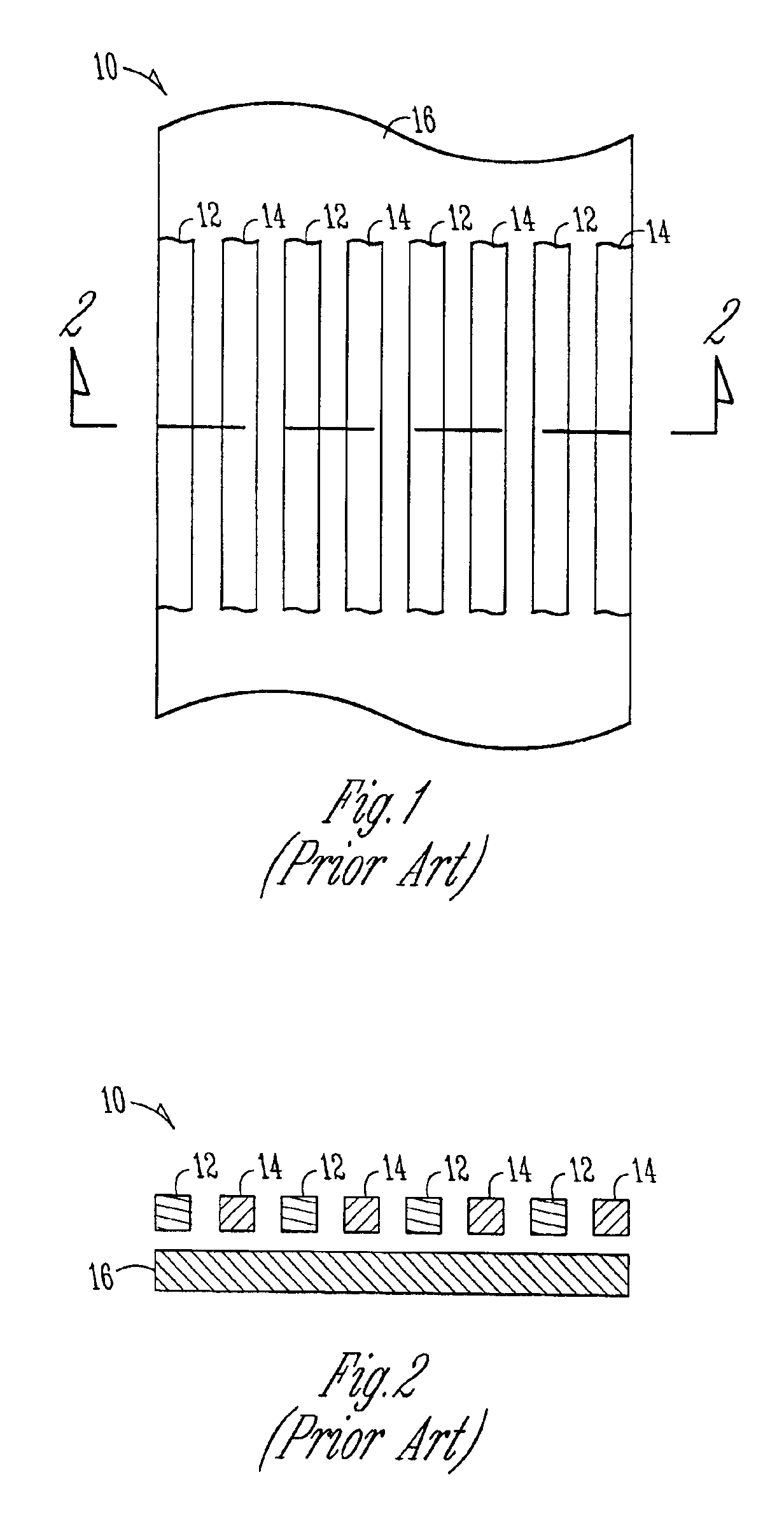
The loss within on-die interconnects, however, is now becoming a greater concern.
To generate standing waves that are adequate to support salphasic clocking, however, transmission structures having relatively low loss are typically required.

Method used


Image

  • Low loss interconnect structure for use in microelectronic circuits
  • Low loss interconnect structure for use in microelectronic circuits
  • Low loss interconnect structure for use in microelectronic circuits

Examples


Embodiment Construction

[0009]In the following detailed description, reference is made to the accompanying drawings that show, by way of illustration, specific embodiments in which the invention may be practiced. These embodiments are described in sufficient detail to enable those skilled in the art to practice the invention. It is to be understood that the various embodiments of the invention, although different, are not necessarily mutually exclusive. For example, a particular feature, structure, or characteristic described herein in connection with one embodiment may be implemented within other embodiments without departing from the spirit and scope of the invention. In addition, it is to be understood that the location or arrangement of individual elements within each disclosed embodiment may be modified without departing from the spirit and scope of the invention. The following detailed description is, therefore, not to be taken in a limiting sense, and the scope of the present invention is defined on...


PUM


Abstract

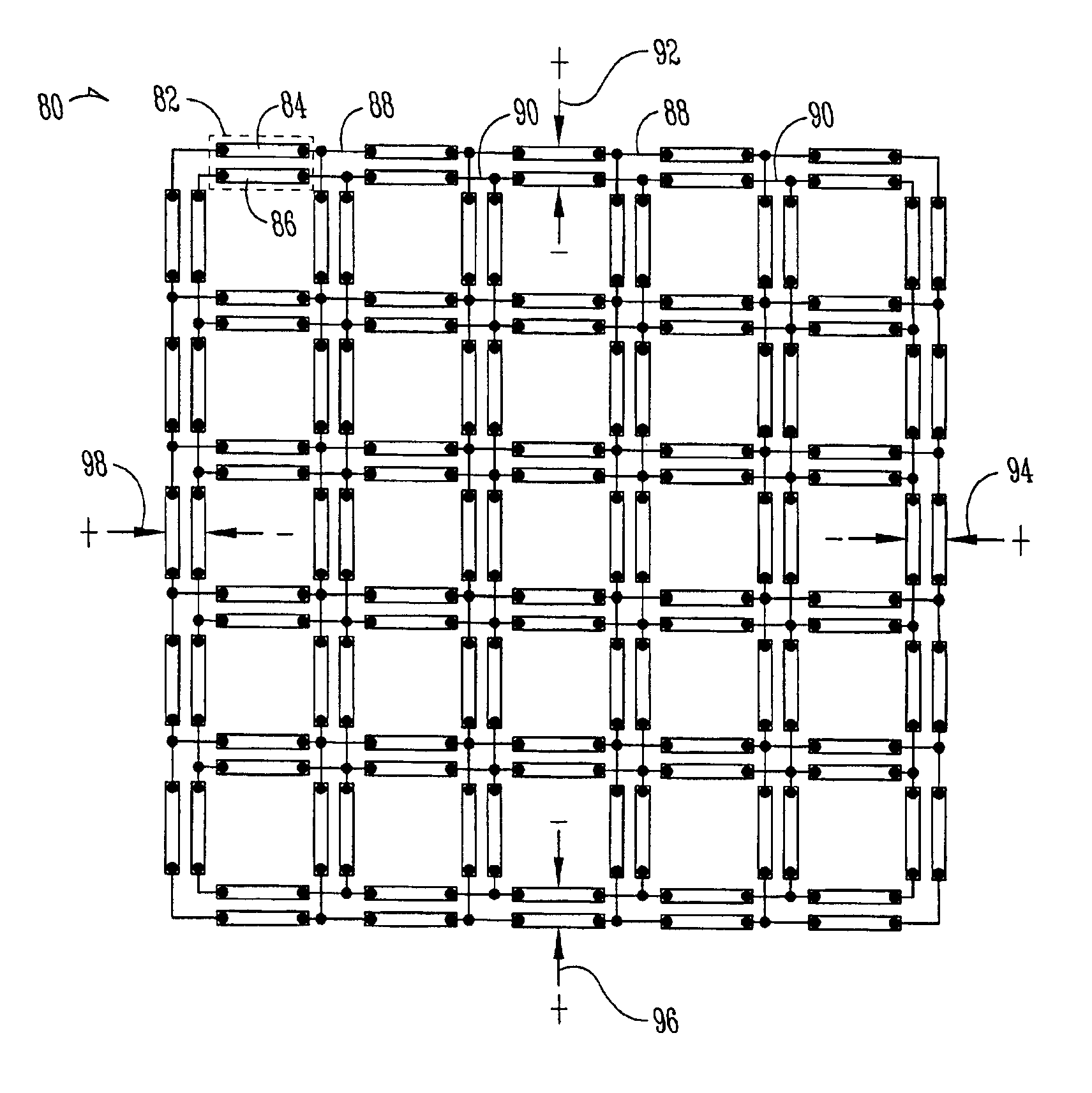
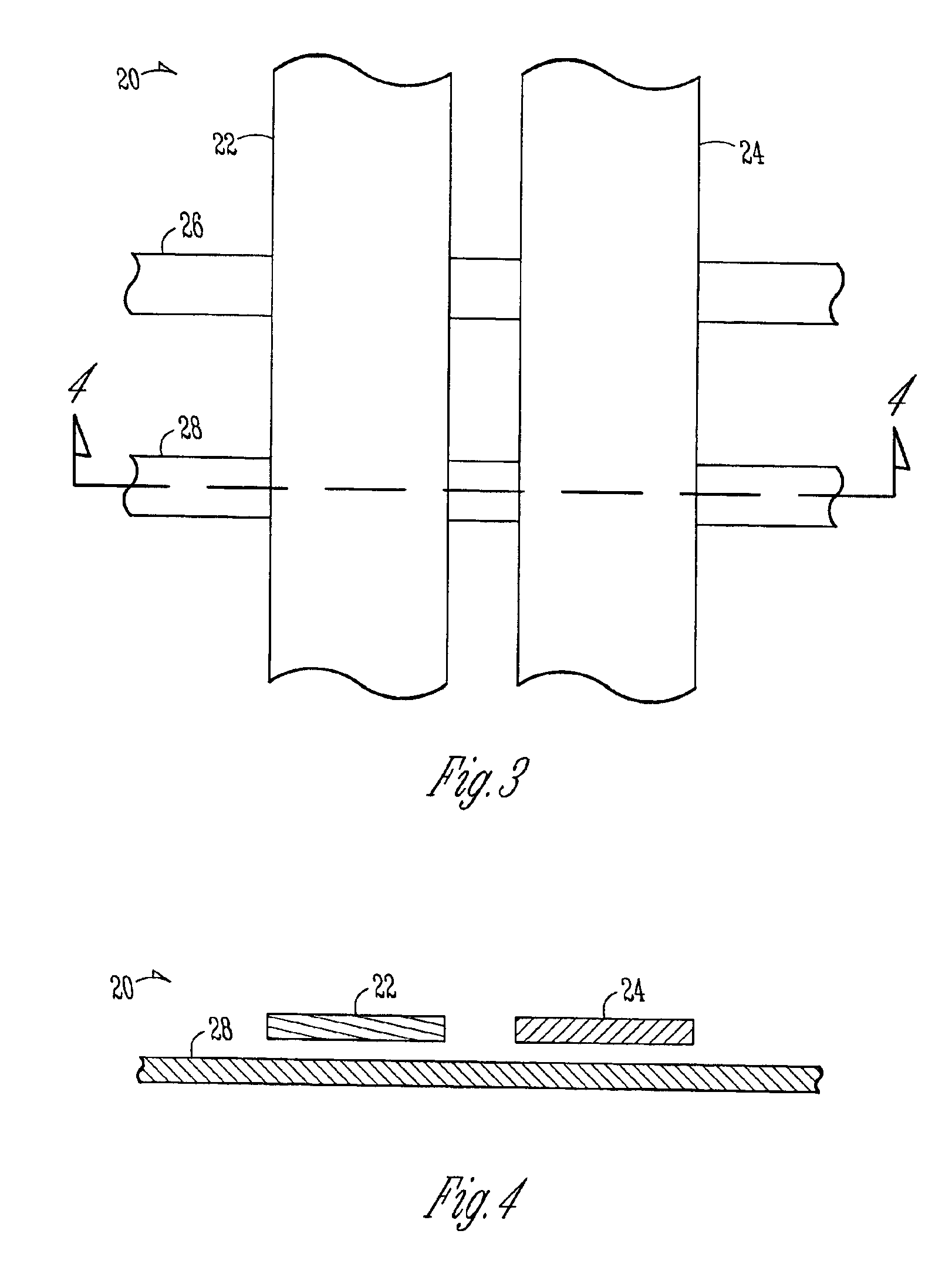
A low loss on-die interconnect structure includes first and second differential signal lines on one of the metal layers of a microelectronic die. One or more traces may also be provided on another metal layer of the die that are non-parallel (e.g., orthogonal) to the differential signal lines. Because the traces are non-parallel, they provide a relatively high impedance return path for signals on the differential signal lines. Thus, a signal return path through the opposite differential line predominates for the signals on the differential lines. In one application, the low loss interconnect structure is used within an on-die salphasic clock distribution network.

Description

FIELD OF THE INVENTION[0001]The invention relates generally to microelectronic circuits and, more particularly, to interconnect structures for use therein.BACKGROUND OF THE INVENTION[0002]Microelectronic devices generally include many on-die interconnects to provide signal delivery and distribution functions for the circuitry. These interconnects are typically used to carry, for example, clock signals, power signals, and / or data signals to various points on the die. In the past, the loss within these on-die interconnects was not a primary concern. Instead, the interconnects were designed to prevent ringing and other signal compromising effects. The loss within on-die interconnects, however, is now becoming a greater concern. For example, one low skew clocking strategy that is currently being considered for use within microelectronic devices is salphasic clocking. Salphasic clocking uses standing waves on a transmission medium to distribute a clock signal in a relatively low skew man...

Claims


Application Information

Patent Timeline
Patent Type & Authority Patents(United States)
IPC IPC(8): H01L23/52H01L23/522
CPCH01L23/5222H01L2924/3011H01L2924/0002H01L2924/00
Inventor O'MAHONY, FRANKANDERS, MARK A.SOUMYANATH, KRISHNAMURTHY
Owner INTEL CORP
Why Eureka
Try Eureka