Rotation angle detector
a detector and rotation angle technology, applied in instruments, galvano-magnetic hall-effect devices, transportation and packaging, etc., can solve the problem of not accurately detecting the rotation angle of the detector, and achieve the effect of simple structure and accurate detection of the rotation angle of the rotor
- Summary
- Abstract
- Description
- Claims
- Application Information
AI Technical Summary
Benefits of technology
Problems solved by technology
Method used
Image
Examples
exemplary embodiment 1
(Exemplary Embodiment 1)
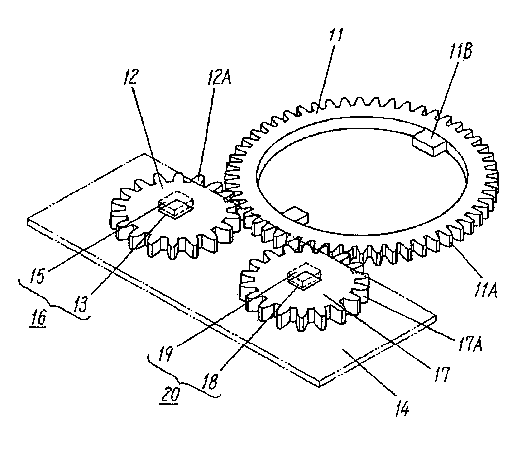
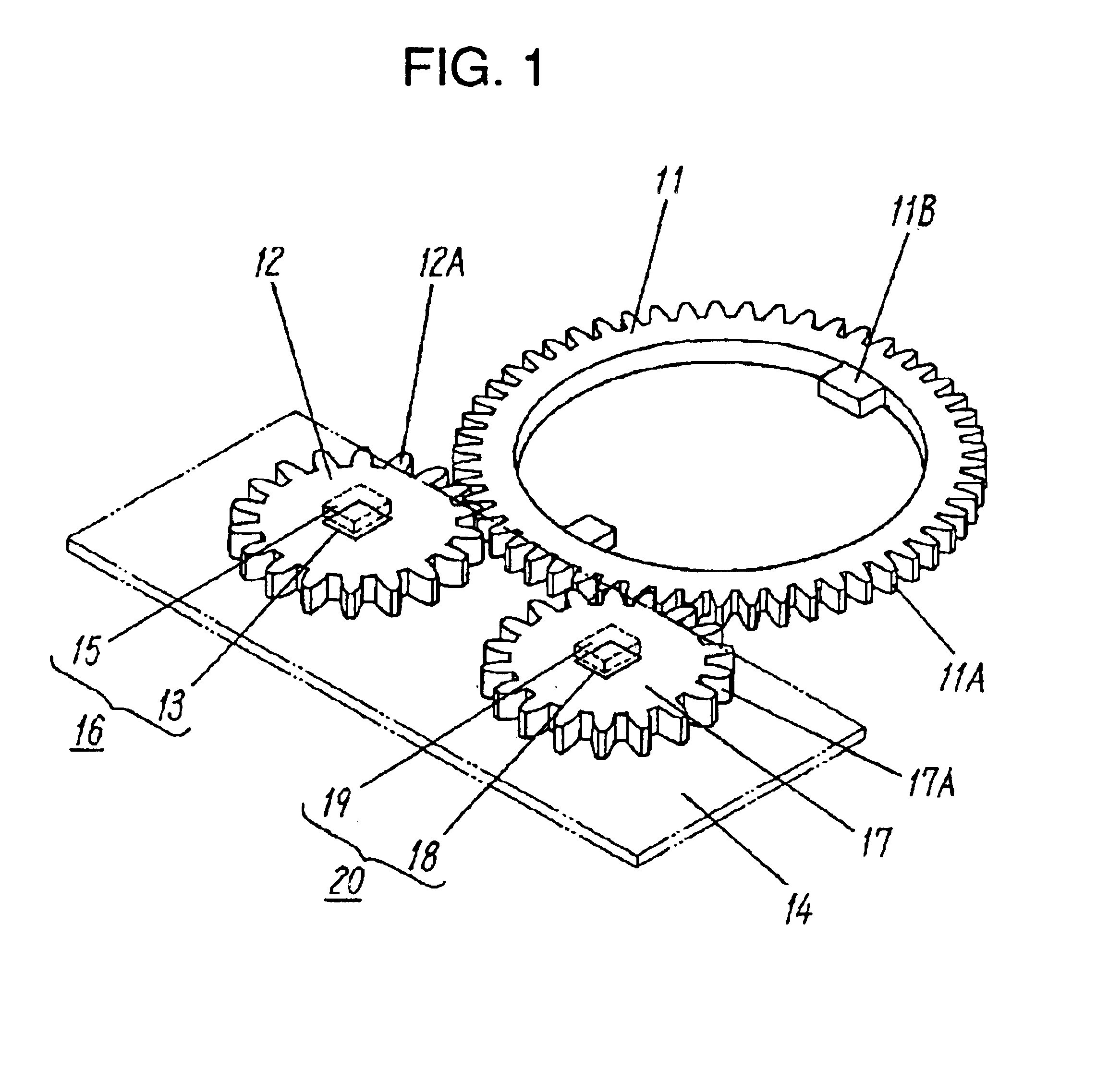
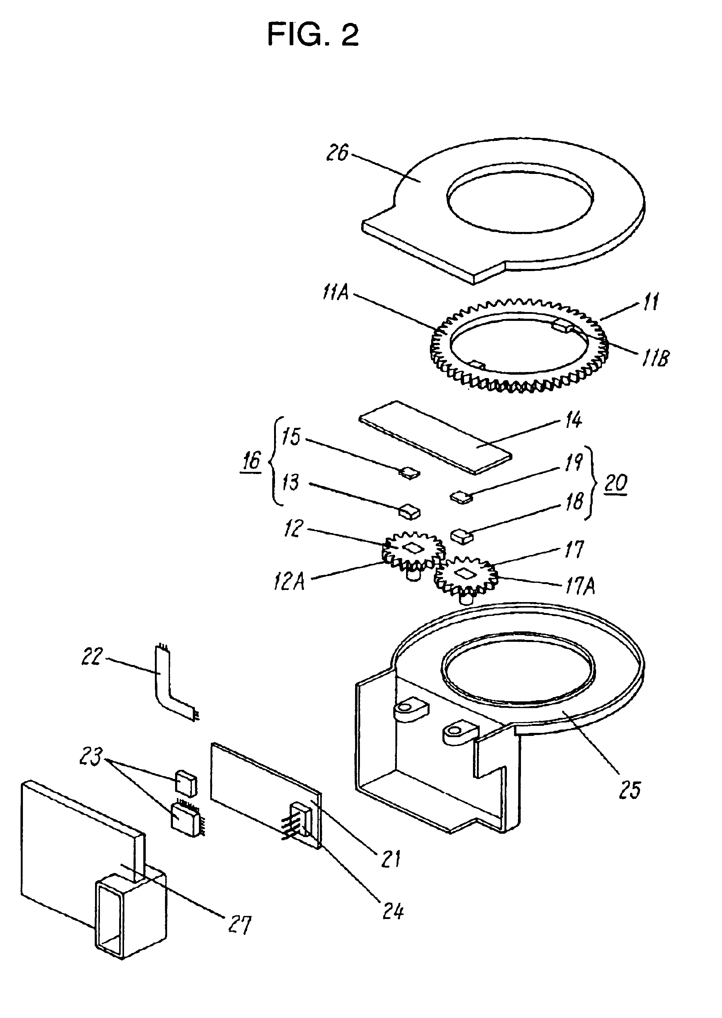
[0020]FIG. 1 is a perspective view of an essential part of a rotation angle detector according to Exemplary Embodiment 1 of the present invention. FIG. 2 is an exploded perspective view of the detector. FIG. 3 is a circuit block diagram of the detector. Spur gear 11A provided on a rim of rotor 11, and fitting part 11B which fits to a shaft of a steering wheel (not illustrated) passing through rotor 11 is provided inside rotor 11. First detecting element 12 includes spur gear 12A on its rim, and spur gear 12A engages spur gear 11A on rotor 11. Magnet 13 is mounted at the center of first detecting element 12 preferably by insert molding. Wiring board 14 is provided on the top face of first detecting element 12 substantially in parallel to element 12, and has wiring patterns (not illustrated) formed on both faces of wiring board 14. Magnetic sensor 15, such as an anisotropic magnetoresistive (AMR) element, is provided on wiring board 14 and faces first detecting...
exemplary embodiment 2
(Exemplary Embodiment 2)
[0039]A rotation angle detector according to Exemplary Embodiment 2 will be described. The same elements as those of Embodiment 1 are denoted by the same reference numerals and are not described in detail.
[0040]FIG. 6 is a perspective view of an essential part of the rotation angle detector of Embodiment 2 of the present invention. The detector, similarly to Embodiment 1, includes spur gear 12A on a rim of first detecting element 12, and spur gear 17 having the same number of teeth as spur gear 12A on a rim of second detecting element 17. Spur gears 12A and 17A engage spur gear 11A of rotor 11. Magnets 13 and 18 are mounted at the centers of first detecting element 12 and second detecting element and 17 preferably by insert molding, respectively. Wiring board 14A is provided on a top face of detecting elements 12 and 17 substantially in parallel to elements 12 and 17. Magnetic sensors 15 and 19 are mounted on a face of wiring board 14A facing detecting elemen...
PUM
 Abstract
Description
Claims
Application Information
 - R&D
- Intellectual Property
- Life Sciences
- Materials
- Tech Scout
- Unparalleled Data Quality
- Higher Quality Content
- 60% Fewer Hallucinations
Browse by: Latest US Patents, China's latest patents, Technical Efficacy Thesaurus, Application Domain, Technology Topic, Popular Technical Reports.
© 2025 PatSnap. All rights reserved.Legal|Privacy policy|Modern Slavery Act Transparency Statement|Sitemap|About US| Contact US: help@patsnap.com


