Rotor angle detecting apparatus for DC brushless motor

Inactive Publication Date: 2005-06-21
HONDA MOTOR CO LTD
View PDF13 Cites 9 Cited by
  • Summary
  • Abstract
  • Description
  • Claims
  • Application Information

AI Technical Summary

Benefits of technology

[0009]The invention was made in view of the aforesaid background, and an object thereof is to provide a rotor angle detecting apparatus for a DC brus

Problems solved by technology

However, when imposing the inspection voltage on the drive voltage in order to detect t

Method used


Image

  • Rotor angle detecting apparatus for DC brushless motor
  • Rotor angle detecting apparatus for DC brushless motor
  • Rotor angle detecting apparatus for DC brushless motor

Examples


Embodiment Construction

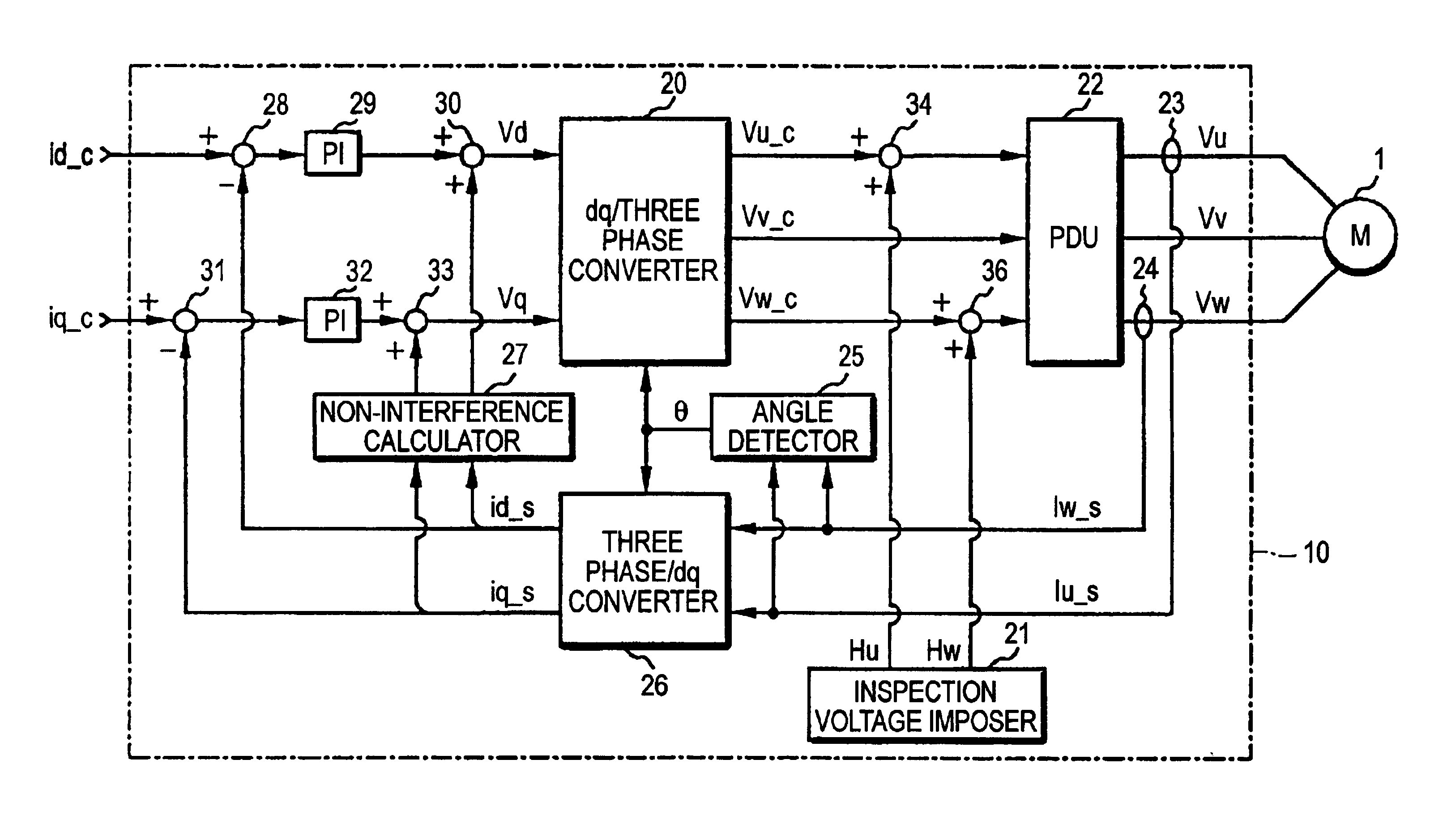
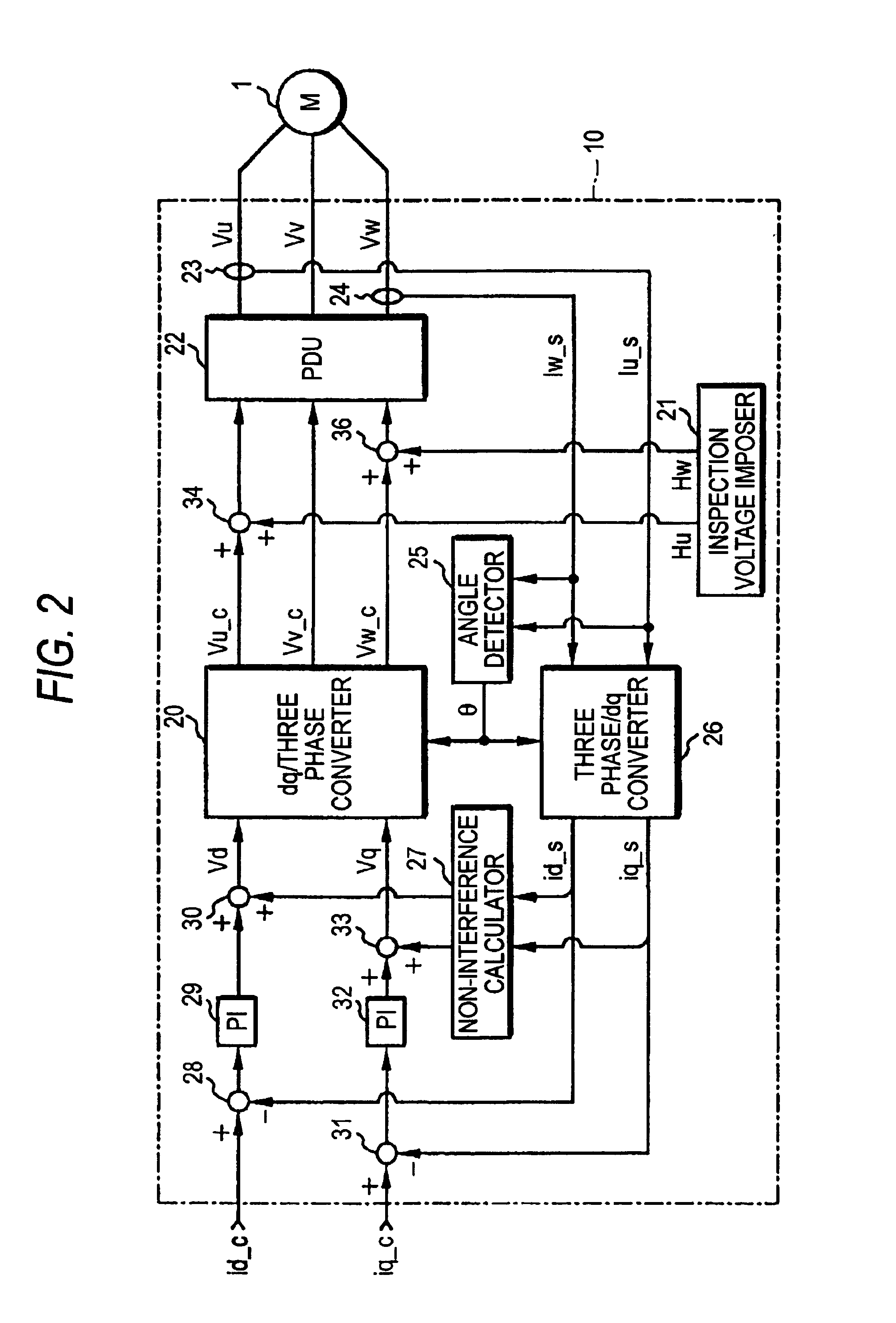
[0057]Embodiments of the invention will be described by reference to FIGS. 1A to 5. FIGS. 1A and 1B show diagrams illustrating the configuration of a DC brushless motor. FIG. 2 is a motor controller control block diagram according to a first embodiment of the invention. FIGS. 3A and 3B showcharts illustrating periods of an inspection voltage and transitions of the inspection voltage and armature current. FIGS. 4A, 4B and 4C show explanatory diagrams explaining the generation of the inspection voltage. FIG. 5 is a motor controller control block diagram according to a second embodiment of the invention.

[0058]Firstly, referring to FIGS. 1 to 4, a first embodiment of the invention will be described. A motor controller 10 shown in FIG. 2 controls current which flows through armatures 3, 4, 5 of a salient pole-type DC brushless motor 1 (hereinafter, simply referred to as a motor 1) shown in FIG. 1 through a feed back loop. The motor controller 10 handles the motor 1 as an equivalent circu...


PUM


Abstract

An inspection voltage imposer generates an inspection voltage by multiplying fundamental voltage string data in which a certain voltage output pattern where an average of output voltage levels in one period becomes 0 is set by data of a modulation signal whose value varies every period and impose the inspection voltage on a drive voltage of a motor. When the inspection voltage is imposed on the drive voltage of the motor, an angle detector detects the rotor angle of the motor based on the fundamental voltage string data, a variation of an inspection current and the data of the modulation signal in respective control cycles.

Description

BACKGROUND OF THE INVENTION[0001]1. Field of the Invention[0002]The present invention relates to a rotor angle detecting apparatus for detecting the rotor angle of a DC brushless motor without using a rotor position detecting sensor.[0003]2. Description of the Related Art[0004]In order to obtain a desired torque by energizing a DC brushless motor, a voltage needs to be applied to an armature in an appropriate phase which corresponds to an electrical angle (hereinafter, referred to as a rotor angle) of a rotor having magnetic poles. With a view to reducing costs for a DC brushless motor and a motor drive unit by omitting a position detecting sensor for detecting the rotor angle, there have been proposed many methods for detecting the rotor angle with using no position detecting sensor.[0005]For example, Japanese Patent Unexamined Publication Nos. Hei. 10-323099 and Hei. 11-332279 describe methods for detecting the rotor angle of a DC brushless motor in a motor control apparatus for c...

Claims


Application Information

Patent Timeline
IPC IPC(8): G01R31/34H02P6/16H02P6/06H02P6/08H02P6/28H02P21/00H02P21/06H02P21/10H02P21/14H02P21/18H02P21/22H02P21/24H02P21/26H02P23/12H02P23/14H02P25/022H02P25/026H02P27/04H02P27/08
CPCG01D5/2006G01R31/34
Inventor IMAI, NOBUYUKITAKAHASHI, YUTAKA
Owner HONDA MOTOR CO LTD
Why Eureka
Try Eureka