Logic synthesis device and logic synthesis method

Inactive Publication Date: 2005-06-21
RICOH KK
View PDF3 Cites 20 Cited by
  • Summary
  • Abstract
  • Description
  • Claims
  • Application Information

AI Technical Summary

Benefits of technology

[0010]Thereby, cell arrangement and optimum load sharing in consideration of wiring area can be performed with a layout tool, unnecessary load sharing

Problems solved by technology

However, even when using the above-mentioned conventional technique, there is no guarantee of achieving timing convergence positively after wiring at a time o

Method used


Image

  • Logic synthesis device and logic synthesis method
  • Logic synthesis device and logic synthesis method
  • Logic synthesis device and logic synthesis method

Examples


Embodiment Construction

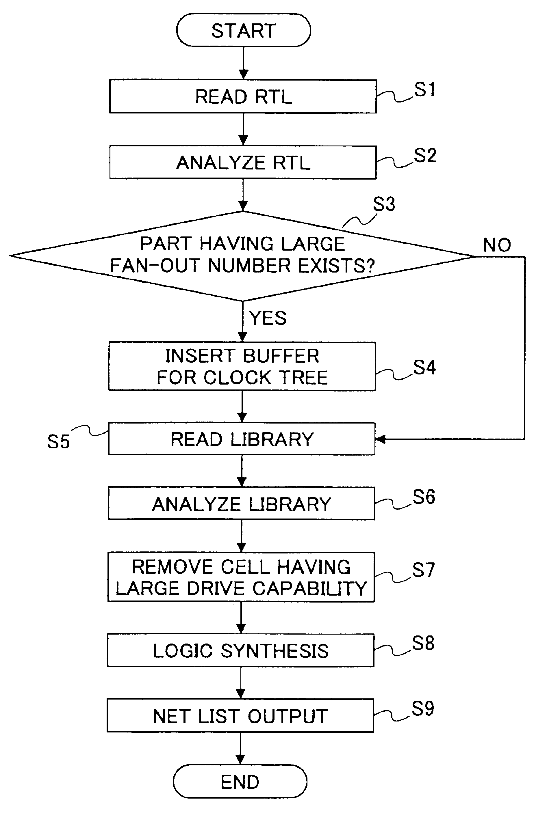
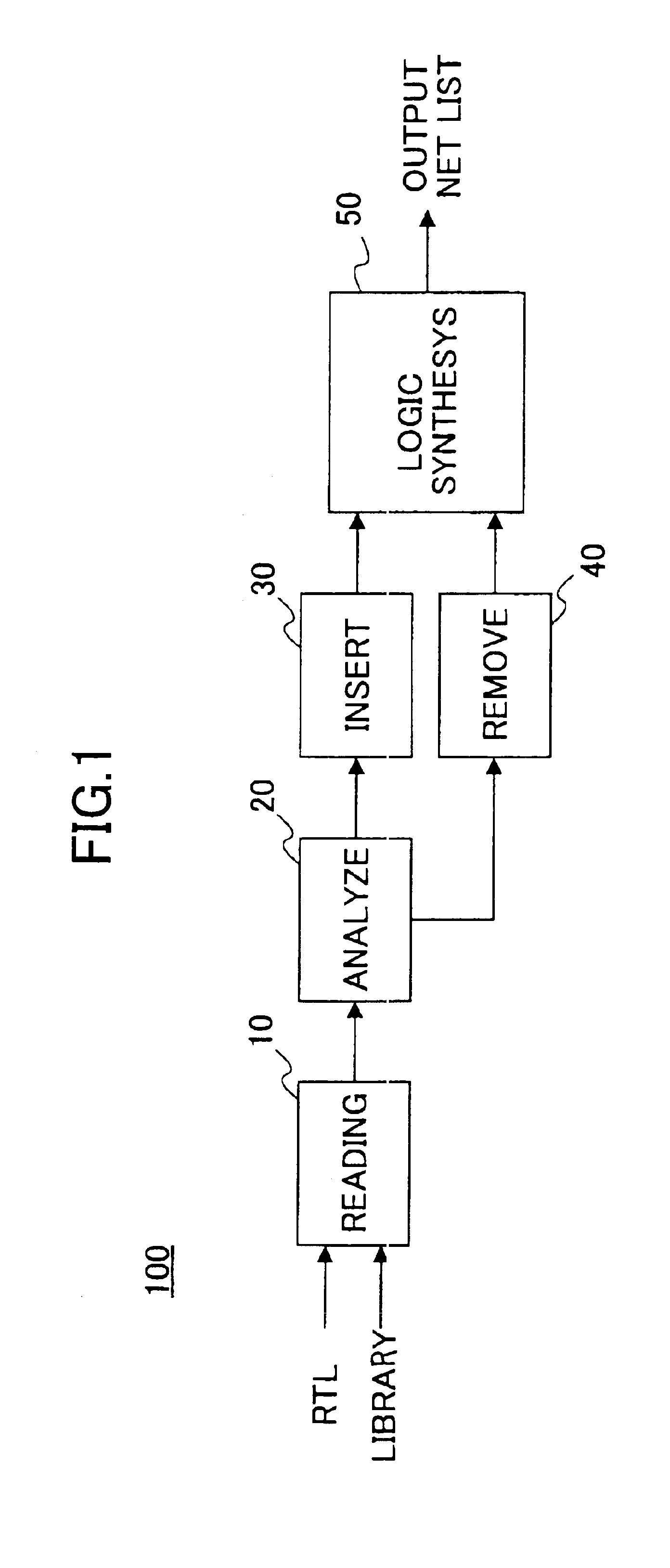
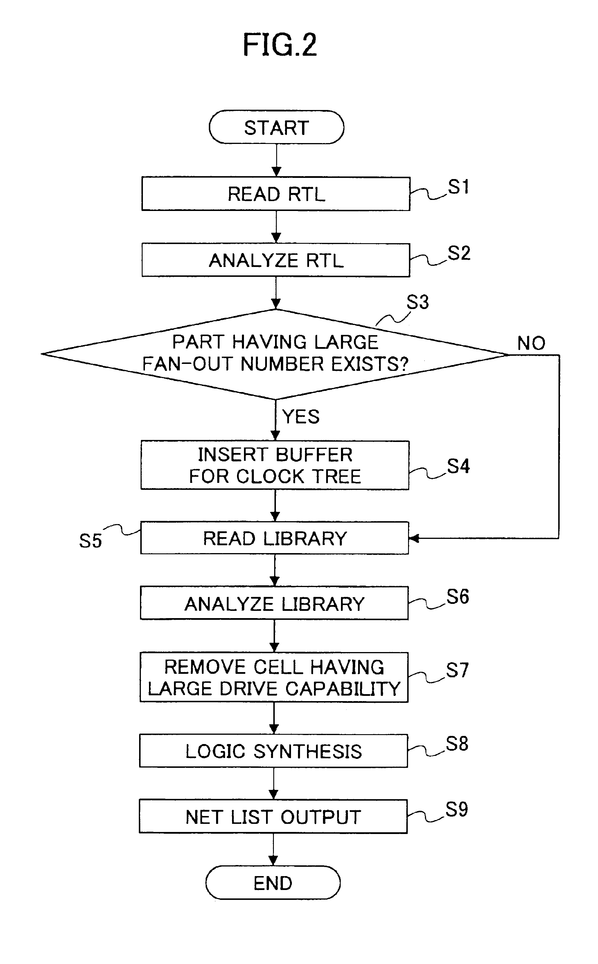
[0023]A block diagram of a logic synthesis device in one embodiment of the present invention is shown in FIG. 1. A processing flow in the logic synthesis device shown in FIG. 1 is shown in FIG. 2.

[0024]First, an RTL which a designer creates is read by a reading part 10 of the logic synthesis device 100 in the embodiment of the present invention, in a step S1. Next, the RTL thus read by the reading part 10 is analyzed by an analyzing part 20 by using a PLI (Programmable Language Interface) on Verilog in a step S2. Then, a description part of the RTL where the fan-out number increases is searched for by this analyzing part in a step S3. FIG. 3 illustrates an example of a description which will result in increase in the fan-out number.

[0025]In FIG. 3, according to a logic of a case sentence starting from line 15, signals sel[O], sel[1] are selecting signals for 64×3 multiplexers (see FIG. 4). Usually, when logic synthesis is performed thereon, as each of the signals sel[0], sel[1] shou...


PUM


Abstract

An analysis part analyzes a description of a logic design; an extraction part extracts a part of the description of the logic design having a fan-out number beyond a predetermined value, based on the analysis; an insertion part inserts a buffer for clock tree synthesis for performing an adjustment on the part extracted by said extracting part, the adjustment being performed at a time of subsequent layout process; and a logic synthesis part performs logic synthesis on the description of the logic design obtained after the insertion performed by said inserting part.

Description

BACKGROUND OF THE INVENTION[0001]1. Field of the Invention[0002]The present invention relates to a logic synthesis device and a logic synthesis method for performing logic synthesis and layout on an LSI (Large Scale Integration) circuit design.[0003]2. Description of the Related Art[0004]An LSI circuit design technique includes a process of logic synthesis, and, for a part having the large number of fan-out, buffering is performed for the purpose of load sharing. Then, a layout process is proceeded to.[0005]Moreover, in the process of logic synthesis, a high drive cell is mapped onto a part where improvement in speed of processing timing is desired greatly, and then, the layout process is proceeded to.[0006]Such a technology is disclosed in Japanese laid-open patent application No. 2000-231583 by NEC Corp. In this technology, when logic synthesis is performed considering a conventional floor-planning, replacing a logic cell with a high drive cell for delay adjustment is not performe...

Claims


Application Information

Patent Timeline
IPC IPC(8): G06F17/50H01L21/82
CPCG06F17/505G06F30/327
Inventor MINAMI, HIDETAKAYAMADA, TAKAMITSUTSUKAMOTO, YASUTAKA
Owner RICOH KK
Why Eureka
Try Eureka