
Method and system for extracting and disposing of water vapor contained in the air of a space vehicle

a space vehicle and water vapor technology, applied in the field of system and method of extracting and disposing of water vapor contained in a volume of pressurized air, can solve the problems of obstructing the discharge pipe, consuming electrical energy, vibration, etc., and achieves the effect of minimizing both the amount of air expelled with the discharged water and the electrical energy consumed

Inactive Publication Date: 2005-06-28
EUROPEAN SPACE AGENCY
View PDF11 Cites 11 Cited by
  • Summary
  • Abstract
  • Description
  • Claims
  • Application Information

AI Technical Summary

Benefits of technology

[0007]The purpose of this invention is to eliminate these disadvantages and to propose an integrated solution making it possible to discharge the water collected in liquid form into space, while at the same time minimizing both the amount of air expelled with the discharged water and the electrical energy consumed. This objective is attained by providing a system for extracting and discharging water vapor contained in a volume of pressurized air, including a cooled condenser apparatus in contact with the volume of pressurized air, wherein the condensed water is transferred into collection areas by means of capillary attraction.

Problems solved by technology

However, these systems use electrical rotating machines such as compressors and centrifuges, which constitutes a major disadvantage for a manned spacecraft, due to the fact that these machines have a significant mass, are noisy, produce vibrations, and consume electrical energy.
Next occurs the problem of extracting the liquid water held in the capillary areas and then that of discharging the water thus collected into space.
As a matter of fact, the water tends to be converted into ice, when directly discharged into space in liquid form, and thus tends to obstruct the discharge pipe.
This document does not provide a solution for discharging the water thus collected into space.

Method used


Image

  • Method and system for extracting and disposing of water vapor contained in the air of a space vehicle
  • Method and system for extracting and disposing of water vapor contained in the air of a space vehicle
  • Method and system for extracting and disposing of water vapor contained in the air of a space vehicle

Examples


Embodiment Construction

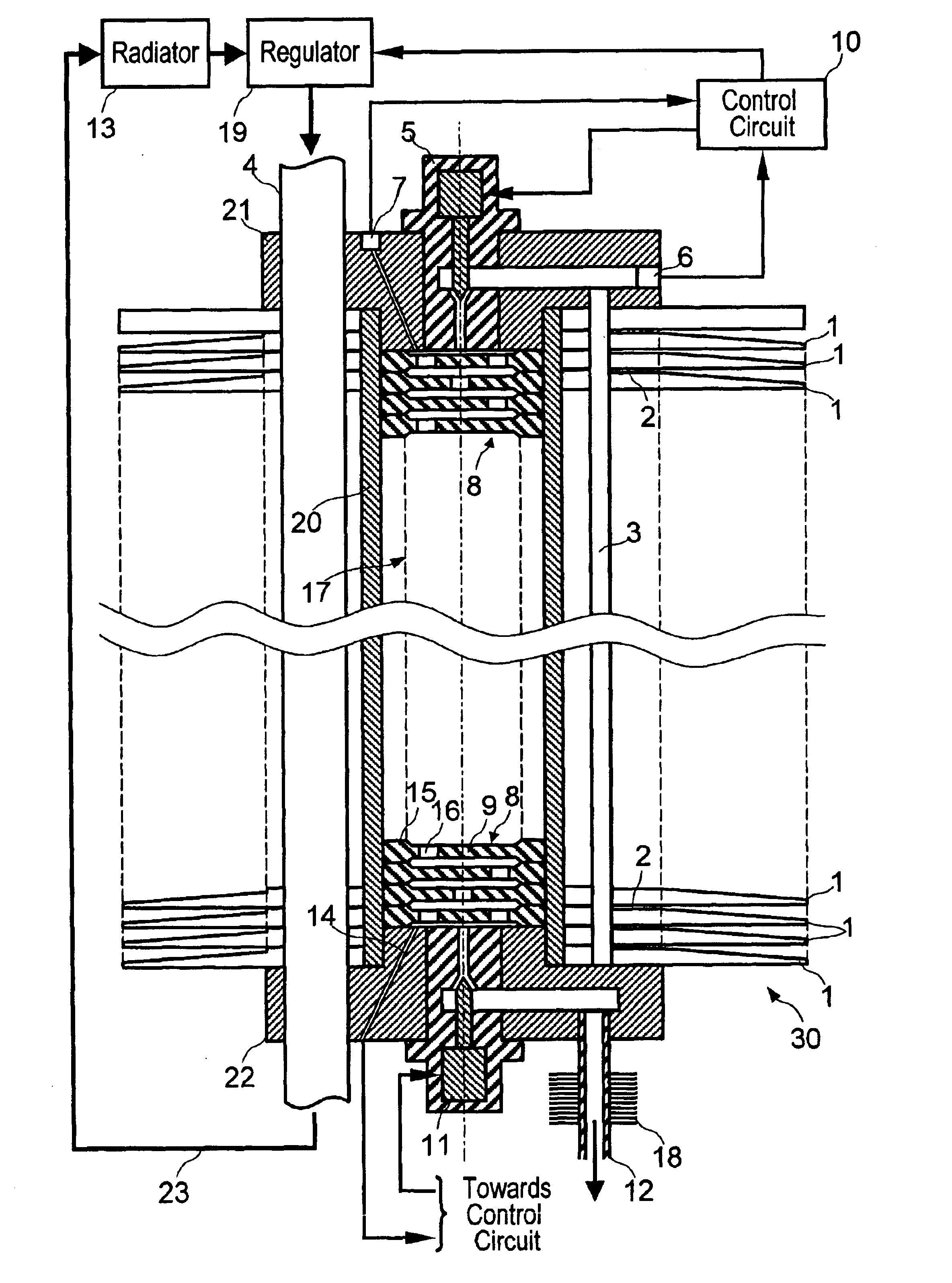
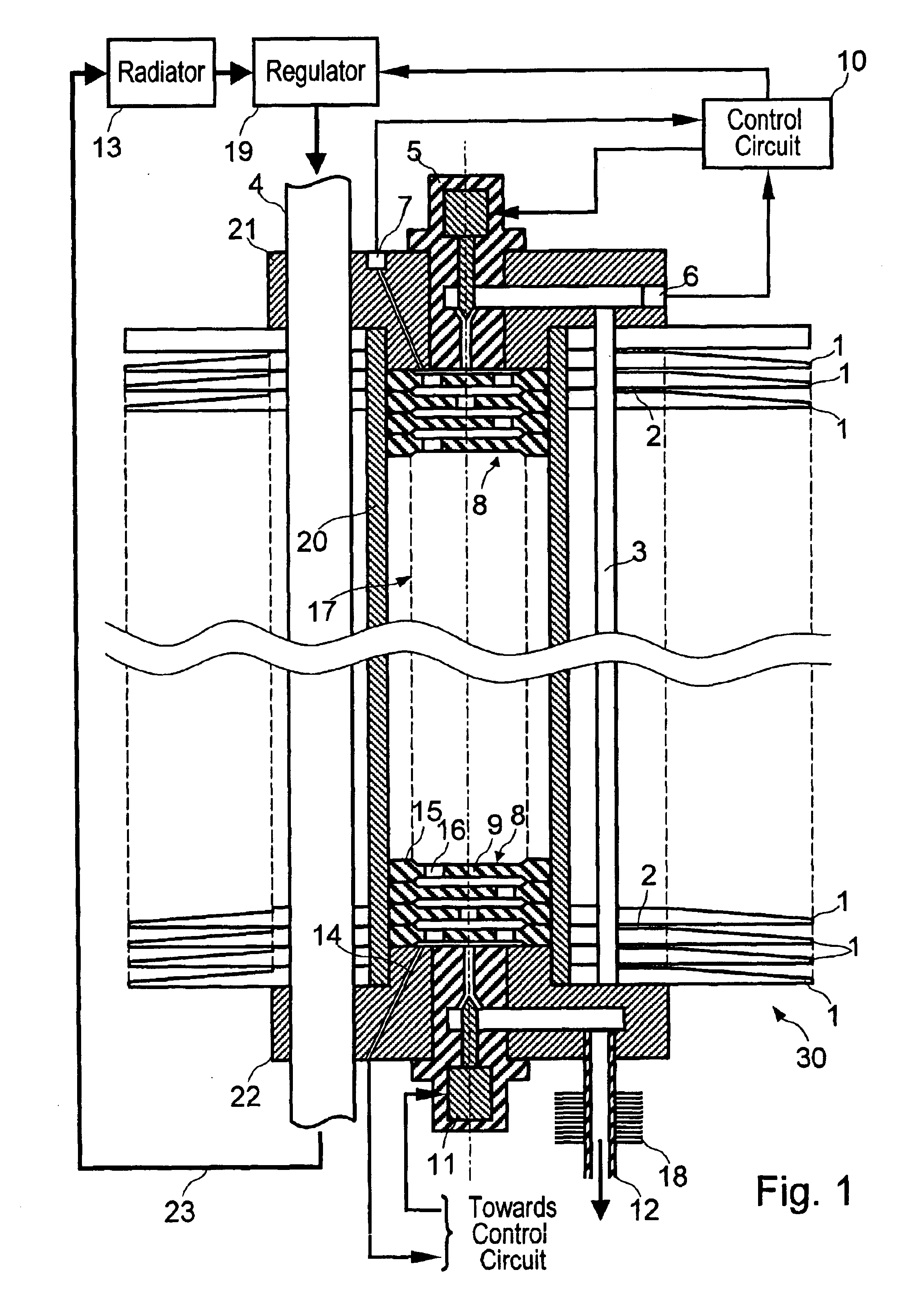
[0031]In FIGS. 1 and 2, the system according to the invention includes a cooled device for condensing and collecting the water vapor contained in the air being dehumidified, coupled with a device for evaporating the collected water, which is connected to a discharge pipe 12 for the collected water vapor, said pipe opening out, for example, into space.

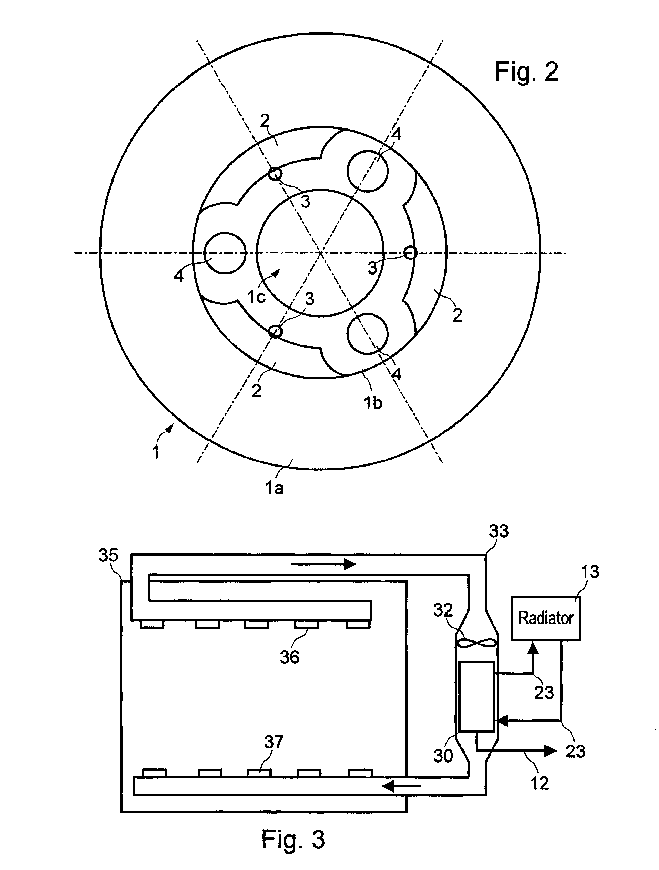
[0032]The condenser and collector apparatus includes a stack of a plurality of fins 1 having a substantially identical, thin truncated cone shape comprising a truncated cone-shaped peripheral part 1a and a substantially planar central part. The central part of each fin includes at least one perforation forming a collection pipe 3 for the condensed water, at least one perforation for the passage of a heat pipe 4, and at least one planar collection area 2, parallel to the central part 1b, and which is slightly recessed in relation thereto, so as to form a space capable of receiving and holding the condensed water by means of capillary att...


PUM

PropertyMeasurementUnit
Temperatureaaaaaaaaaa
Pressureaaaaaaaaaa
Volumeaaaaaaaaaa

Abstract

A system for extracting including a cooled condenser apparatus in contact with the volume of pressurized air being dehumidified, the condensed water being transferred into collection areas by means of capillary attraction; an evaporation chamber in thermal contact with the condenser apparatus having an inlet connected to the collection areas by means of a first valve device and an outlet connected by means of a second valve device to a space wherein the pressure is lower than that of the volume of pressurized air; and a control device for controlling the valve devices in order to carry out a control cycle with a first phase for placing the evaporation chamber under negative pressure in relation to the volume of pressurized air, and a second phase for suctioning the condensed water in the collection areas towards the decompression chamber, until the pressure in the decompression chamber reaches a predefined threshold.

Description

FIELD OF THE INVENTION[0001]This invention relates to a system and method of extracting and disposing of water vapor contained in a volume of pressurized air.[0002]It applies in particular, but not exclusively, to the pressure cabins of manned spacecraft, i.e., in the absence of gravity or in a microgravity environment. As a matter of fact, human beings or animals discharge water vapor continuously. When they live in a volume of pressurized air, it is necessary to extract the water vapor as they discharge it.DESCRIPTION OF THE RELATED ART[0003]Various systems have been developed to extract the water vapor from the air and to discharge it into space. However, these systems use electrical rotating machines such as compressors and centrifuges, which constitutes a major disadvantage for a manned spacecraft, due to the fact that these machines have a significant mass, are noisy, produce vibrations, and consume electrical energy.[0004]Moreover, the Applicant has designed a condenser appar...

Claims


Application Information

Patent Timeline
IPC IPC(8): B01D53/26B64G1/46B64G1/48B64G1/12B64G1/00
CPCB01D53/265B64G1/48F24F2003/1446B64G1/12
Inventor LAINE, ROBERTTAMBURINI, PRIMO
Owner EUROPEAN SPACE AGENCY
Learn More