
Apparatus and method for preventing inlet vortex

Inactive Publication Date: 2005-06-28
UNITED TECH CORP
View PDF8 Cites 24 Cited by
  • Summary
  • Abstract
  • Description
  • Claims
  • Application Information

AI Technical Summary

Benefits of technology

[0009]It is a further object of the present invention to provide an apparatus and method for preventing the formation of a ground plane induced inlet vortex during engine testing.
[0022]These and other objects of the present invention are achieved in another aspect by a suppressor for preventing a vortex between an inlet of a gas turbine engine on an aircraft and a tarmac. The suppressor comprises: a base facing said tarmac; and an inclined surface extending in a direction from said tarmac towards said inlet at an angle to said base. The suppressor prevents formation of said vortex.

Problems solved by technology

The drawback, however, of a test cell is that the engine must be removed from the aircraft.
Removing the engine from the aircraft adds cost and time to the testing procedure.
The main drawback of typical engine installations is the limited power settings available during the test.
The technician can only operate typical engine installations at low power settings.
The vortices can damage the engine by inducing a compressor surge, by creating unstable operating conditions, or by picking up debris.

Method used


Image

  • Apparatus and method for preventing inlet vortex
  • Apparatus and method for preventing inlet vortex
  • Apparatus and method for preventing inlet vortex

Examples


Embodiment Construction

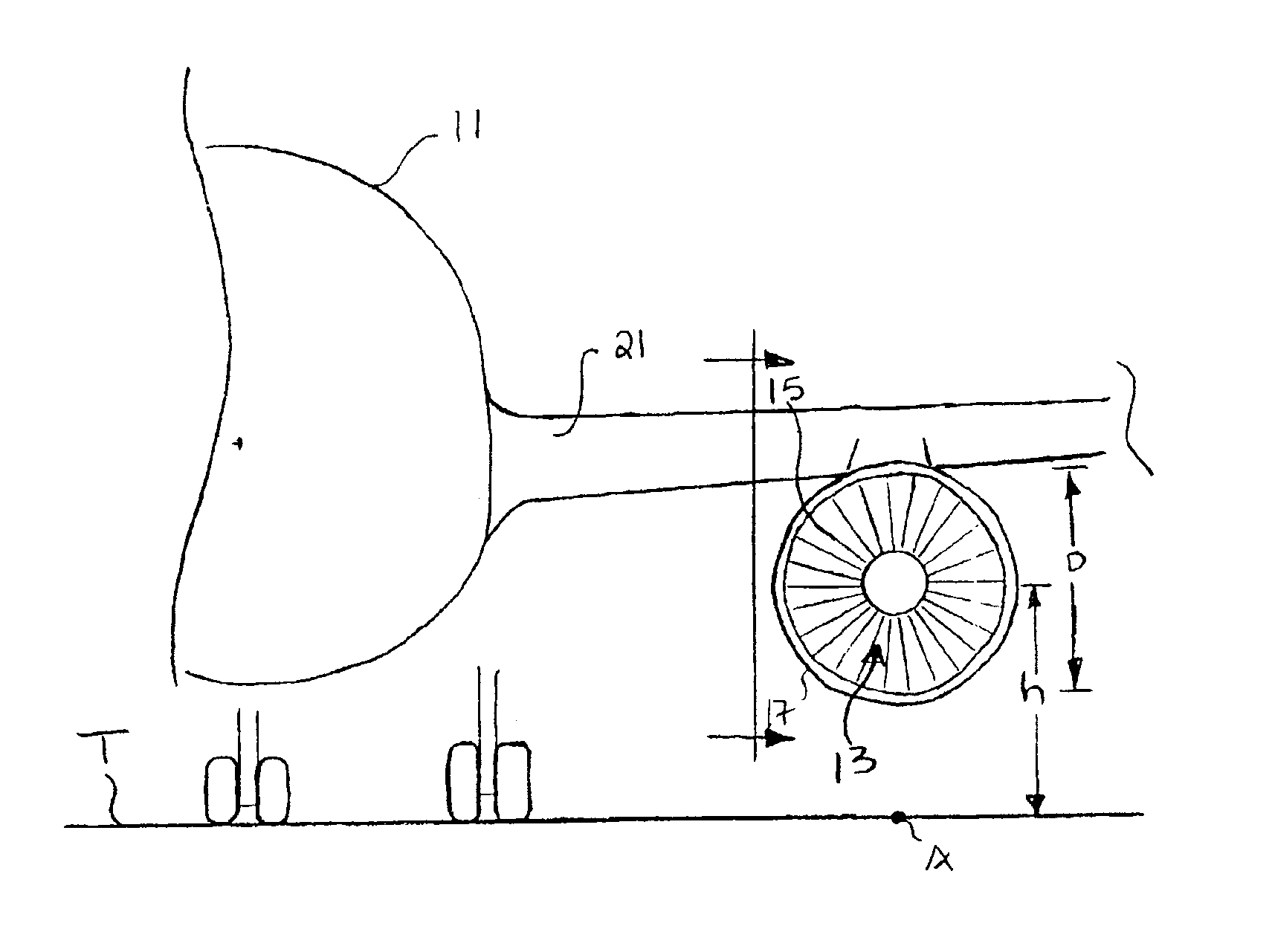
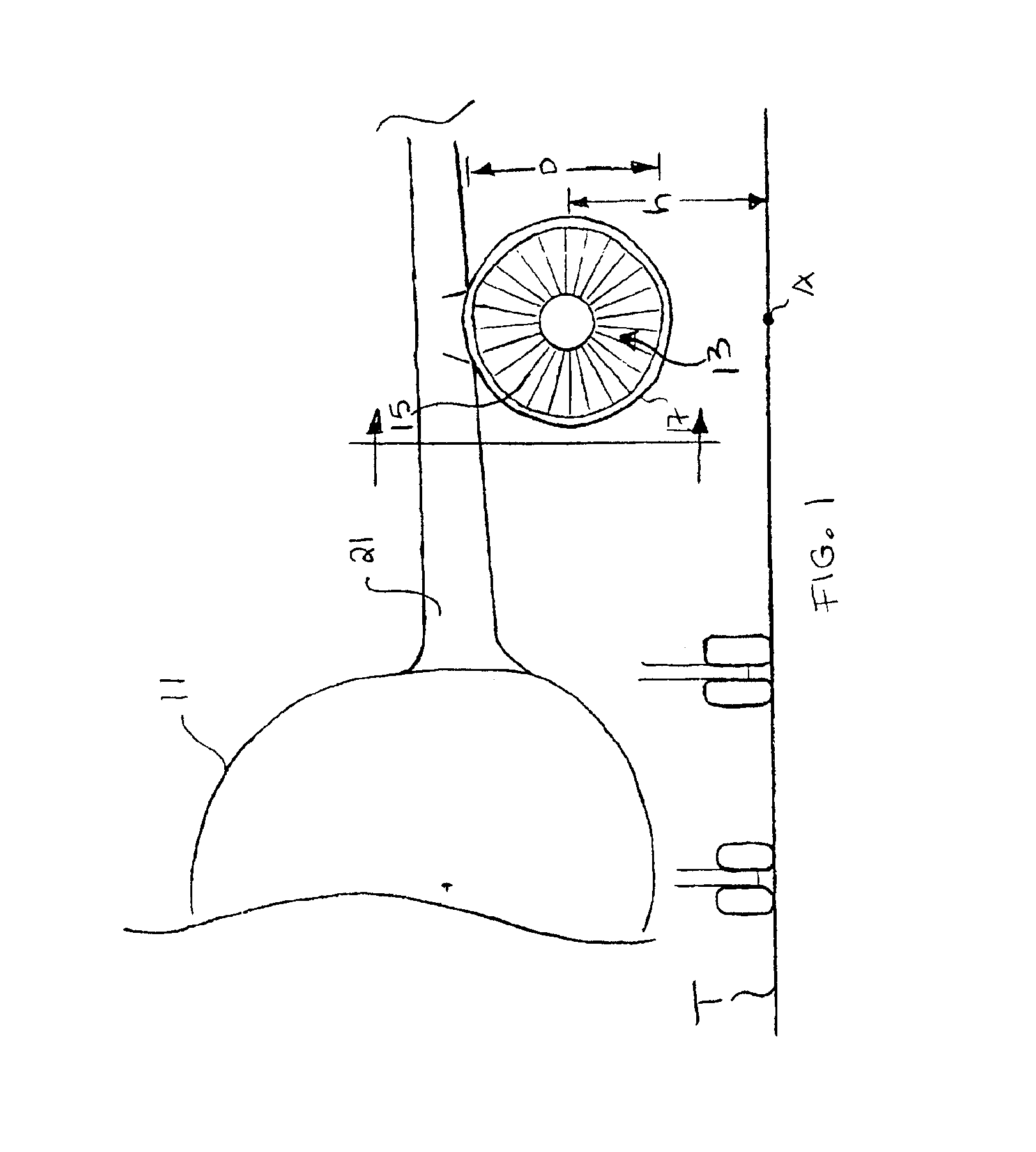
[0033]FIG. 1 displays an aircraft 11 on a tarmac T. The aircraft 11 has one or more powerplants 13. Each powerplant 13 comprises a gas turbine engine 15 surrounded by a nacelle 17. The engine 15 could be a high bypass turbofan.

[0034]The centerline of the powerplant 13 resides at a height h above the tarmac T. The powerplant 13 could mount to the aircraft 11 in any known fashion. For example, the powerplant 13 could extend from a strut 19 below a wing 21. The nacelle 17 includes an inlet 23 that allows air to enter the engine 15. The inlet 23 has an internal throat diameter D.

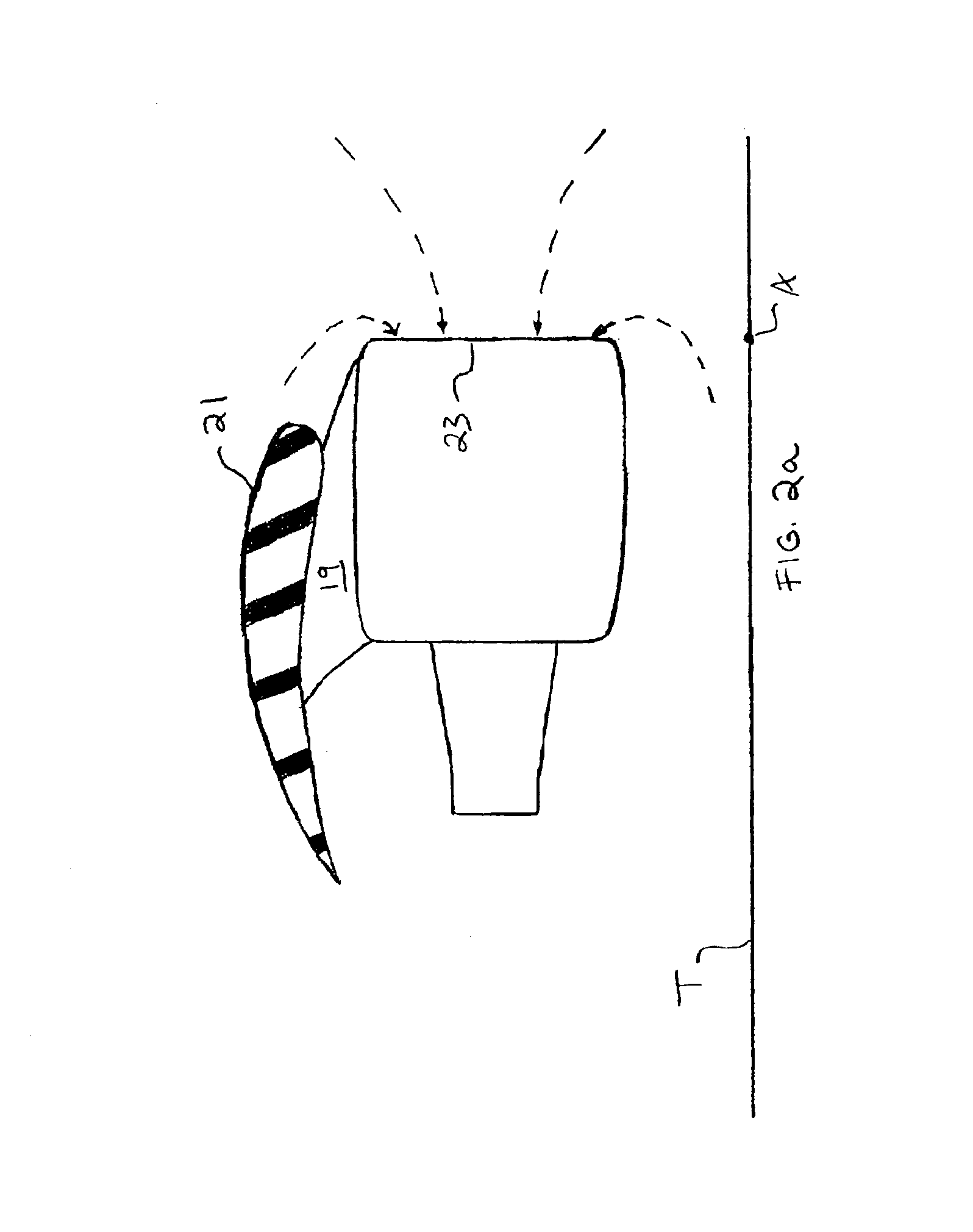
[0035]FIG. 2a displays the powerplant 13 operating at a low power setting. The engine 15 draws in air (shown as dashed lines) from locations surrounding the inlet 23. Since the aircraft 11 remains static on the tarmac T, the engine 15 draws in air from both upstream and downstream of the inlet 23.

[0036]Engine Pressure Ratio (EPR) is a common performance parameter when discussing power settings. EPR is the ratio ...


PUM


Abstract

A method of operating a gas turbine engine for testing, comprising: providing an aircraft on a tarmac, the aircraft having a gas turbine engine with an inlet; selecting a power setting for the engine that is capable of producing a vortex between the inlet and the tarmac; and inhibiting formation of the vortex. A suppressor for preventing a vortex between an inlet of a gas turbine engine on an aircraft and a tarmac. The suppressor comprises: a base facing the tarmac; and an inclined surface extending in a direction from the tarmac towards the inlet at an angle to the base. The suppressor prevents formation of the vortex.

Description

BACKGROUND OF INVENTION[0001]This invention relates to an apparatus and a method for preventing an inlet vortex. Specifically, this invention relates to an apparatus and method for preventing the formation of a vortex at an inlet of a gas turbine engine while the engine operates on an aircraft located on a tarmac.[0002]Technicians have several options when performing tests with in-service engines. For example, the technician can perform the engine testing on a test stand. Or the technician can perform the engine testing while the engine operates on the aircraft static on the ground. Each testing method has benefits and drawbacks.[0003]Testing an engine in a test stand generally allows for the greatest amount of data acquisition. The test stand can measure the thrust of the engine and includes all of the instrumentation necessary to collect and to interpret engine conditions during operation. The test stand also provides a uniform standard for ensuring that each engine meets all of t...

Claims


Application Information

Patent Timeline
IPC IPC(8): G01L3/26G01M15/00G01L3/00G01L5/13G01M15/14
CPCG01M15/14G01L5/133
Inventor CLARK, TERRY A.URBAN, JUSTIN R.
Owner UNITED TECH CORP
Learn More